Intel BX80601920 Data Sheet - Page 80
Fan Speed Control with Digital Thermal Sensor, 3.1.2, Processor Thermal Data Sample Rate
 |
UPC - 735858204736
View all Intel BX80601920 manuals
Add to My Manuals
Save this manual to your list of manuals |
Page 80 highlights
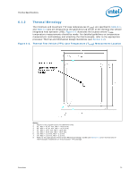
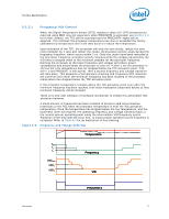
Thermal Specifications 6.3.1.1 6.3.1.2 Note: Fan Speed Control with Digital Thermal Sensor Fan speed control solutions temperature data, which is dueselivaerveadluoevsetroPreEdCIin(itnheresstpaotincsveatroiabaleG,eTtTCeOmNTpR0O(L). The DTS acosmamrealnadti)v,eisvacloume pvaerresdustoanthaisbsToClOuNteTRvOaLlureef.eTrehnectee.mTpheeraDtTuSreteremppoerrtaetduoreveisr reported PECI is always a negative value and represents a delta below the onset of thermal control circuit (TCC) activation, as indicated by PROCHOT#. Therefore, as the temperature approaches TCC activation, the value approaches zero degrees. Processor Thermal Data Sample Rate and Filtering The processor digital thermal sensor (DTS) provides an improved capability to monitor device hot spots, which inherently leads to more varying temperature readings over short time intervals. To reduce the sample rate requirements on PECI and improve thermal data stability versus. time the processor DTS implements an averaging algorithm that filters the incoming data. This filter is expressed mathematically as: PECI(t) = PECI(t-1)+1/(2^^X)*[Temp - PECI(t-1)] Where: PECI(t) is the new averaged temperature; PECI(t-1) is the previous averaged temperature; Temp is the raw temperature data from the DTS; X is the Thermal Averaging Constant (TAC) Only values read using the PECI interface are averaged. Temperature values read using the IA32_THERM_STATUS MSR are not averaged. The Thermal Averaging Constant is a BIOS configurable value that determines the time in milliseconds over which the DTS temperature values are averaged. Short averaging times will make the averaged temperature values respond more quickly to DTS changes. Long averaging times will result in better overall thermal smoothing but also incur a larger time lag between fast DST temperature changes and the value read using PECI. Refer to the appropriate processor Thermal and Mechanical Design Guidelines (see Section 1.2) for further details on the Data Filter and the Thermal Averaging Constant. Within the processor, the DTS converts an analog signal into a digital value representing the temperature relative to TCC activation. The conversions are in integers with each single number change corresponding to approximately 1 °C. DTS values reported using the internal processor MSR will be in whole integers. As a result of the averaging function described above, DTS values reported over PECI will include a 6-bit fractional value. Under typical operating conditions, where the ttehme pteemrapteurraetiusrecloaspeprtooaTcChOeNsTRzOerLo, ,ththeefrfarcatcitoinoanlavl avlauleusesmcaaynnboet be of used interest. But when to detect the activation of the TCC. An averaged temperature value between 0 and 1 can only occur if the TCC has been activated during the averaging window. As TCC activation time increases, the fractional value will approach zero. Fan control circuits can detect this situation and take appropriate action as determined by the system designers. Of course, fan control chips can also monitor the PROCHOT# pin to detect TCC activation using a dedicated input pin on the package. Further details on how the Thermal Averaging Constant influences the fractional temperature values are available in the Thermal Design Guide. 80 Datasheet
-
 1
1 -
2
-
3
-
4
-
5
-
6
-
7
-
8
-
9
-
10
-
11
-
12
-
13
-
14
-
15
-
16
-
17
-
18
-
19
-
20
-
21
-
22
-
23
-
24
-
25
-
26
-
27
-
28
-
29
-
30
-
31
-
32
-
33
-
34
-
35
-
36
-
37
-
38
-
39
-
40
-
41
-
42
-
43
-
44
-
45
-
46
-
47
-
48
-
49
-
50
-
51
-
52
-
53
-
54
-
55
-
56
-
57
-
58
-
59
-
60
-
61
-
62
-
63
-
64
-
65
-
66
-
67
-
68
-
69
-
70
-
71
-
72
-
73
-
74
-
 75
75 -
 76
76 -
 77
77 -
 78
78 -
 79
79 -
 80
80 -
 81
81 -
 82
82 -
 83
83 -
 84
84 -
 85
85 -
86
-
87
-
88
-
89
-
90
-
91
-
92
-
93
-
94
-
95
-
96
 |
 |
