Brother International IntelliFax-3550 Service Manual - Page 129
Operational Check of Control Panel PCB, VALID OPERATE on the LCD.
 |
View all Brother International IntelliFax-3550 manuals
Add to My Manuals
Save this manual to your list of manuals |
Page 129 highlights
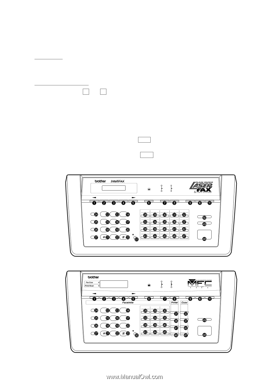
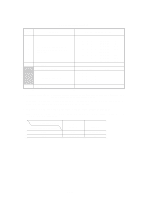
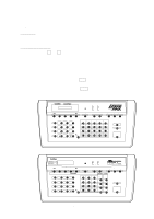
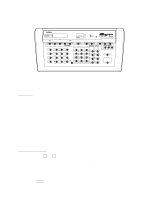
3.7 Operational Check of Control Panel PCB s Function This function checks the control panel PCB for normal operation. s Operating Procedure (1) Press the 1 and 3 keys in this order in the initial maintenance mode. The "00 " will appear on the LCD. (2) Press the keys and buttons in the order designated in the illustration shown below. The LCD shows the corresponding number in decimal notation each time a key or button is pressed. Check that the displayed number is correct by referring to the illustration below. If a key or button is pressed out of order, the equipment beeps and displays the "INVALID OPERATE" on the LCD. To return to the status ready to accept key & button entry for operational check, press the Stop key. (3) After the last number key or button is pressed, the equipment beeps for 1 second. (4) To terminate this operation, press the Stop key. The equipment returns to the initial maintenance mode. FAX3550/3650/8000P/8200P 3550 Set Function Clear Tel-index Fine Fax Photo TAD S.Fine F/ T Resolution Mode Super Q.Scan Help Enlarge / Reduce Hook ABC DEF 123 01 02 03 04 05 21 22 23 24 25 Hold GH I JKL MNO 4 56 06 07 08 09 10 26 27 28 29 30 Redial / Pause PQRS TUV W X YZ 789 11 12 13 14 15 31 32 33 34 35 16 17 18 19 20 Speed Dial 0 Shift 36 37 38 39 40 Copy Stop Start MFC4450/4550/4550plus/9000 status status MFC 4550 Set Function Clear Tel-index Fine Fax Photo TAD S.Fine F/ T Resolution Mode FAX PRINTER COPIER SCANNER PC FAX Coverpage Super Q.Scan Help Hook ABC DEF 123 01 02 03 13 14 15 On/Off Line Photo Hold GH I JKL MNO 4 56 04 05 06 16 17 18 FF/Cont Enlarge Stop 07 08 09 Redial / Pause PQRS TUV W X YZ 789 19 20 21 Test/ Reset Reduce Start 10 11 12 Speed Dial 0 Shift 22 23 24 Print Priority Copy Key & Button Entry Order (1) V - 47
-
 1
1 -
2
-
3
-
4
-
5
-
6
-
7
-
8
-
9
-
10
-
11
-
12
-
13
-
14
-
15
-
16
-
17
-
18
-
19
-
20
-
21
-
22
-
23
-
24
-
25
-
26
-
27
-
28
-
29
-
30
-
31
-
32
-
33
-
34
-
35
-
36
-
37
-
38
-
39
-
40
-
41
-
42
-
43
-
44
-
45
-
46
-
47
-
48
-
49
-
50
-
51
-
52
-
53
-
54
-
55
-
56
-
57
-
58
-
59
-
60
-
61
-
62
-
63
-
64
-
65
-
66
-
67
-
68
-
69
-
70
-
71
-
72
-
73
-
74
-
75
-
76
-
77
-
78
-
79
-
80
-
81
-
82
-
83
-
84
-
85
-
86
-
87
-
88
-
89
-
90
-
91
-
92
-
93
-
94
-
95
-
96
-
97
-
98
-
99
-
100
-
101
-
102
-
103
-
104
-
105
-
106
-
107
-
108
-
109
-
110
-
111
-
112
-
113
-
114
-
115
-
116
-
117
-
118
-
119
-
120
-
121
-
122
-
123
-
 124
124 -
 125
125 -
 126
126 -
 127
127 -
 128
128 -
 129
129 -
 130
130 -
 131
131 -
 132
132 -
 133
133 -
 134
134 -
135
-
136
-
137
-
138
-
139
-
140
-
141
-
142
-
143
-
144
-
145
-
146
-
147
-
148
-
149
-
150
-
151
-
152
-
153
-
154
-
155
-
156
-
157
-
158
-
159
-
160
-
161
-
162
-
163
-
164
-
165
-
166
-
167
-
168
-
169
-
170
-
171
-
172
-
173
-
174
-
175
-
176
-
177
-
178
-
179
-
180
-
181
-
182
-
183
-
184
-
185
-
186
-
187
-
188
-
189
-
190
-
191
 |
 |