Brother International IntelliFax-3550 Service Manual - Page 50

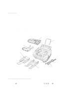
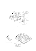
Iv. Disassembly/reassembly And Lubrication, Disassembly/reassembly, Lubrication

Page 50 highlights

CONTENTS 1. DISASSEMBLY/REASSEMBLY IV-1 s Safety Precautions IV-1 s Preparation IV-3 s How to Access the Object Component IV-3 s Disassembly Order Flow IV-4 1.1 Top Cover IV-5 1.2 Handset Mount and Hook Switch PCB (for handset-equipped versions) Side Cover (for non-handset versions IV-5 1.3 Multi-purpose Sheet Feeder IV-6 1.4 Control Panel ASSY IV-6 1.5 Panel Rear Cover and Control Panel IV-7 1.6 Document Feed Roller ASSY and Ejection Roller ASSY IV-8 1.7 Inner Cover IV-8 1.8 Scanner Frame ASSY IV-10 1.9 Insulation Cover IV-12 1.10 Fixing Unit, FU Lamp, and Paper Ejection Sensor Actuator IV-13 1.11 Laser Unit IV-15 1.12 Bottom Plate IV-16 1.13 Low-voltage Power Supply PCB IV-17 1.14 High-voltage Power Supply PCB and Fan 1 IV-18 1.15 Main PCB IV-19 1.16 Relay PCB IV-21 1.17 Shield Bracket and NCU PCB ASSY IV-22 1.18 Gear Drive Unit IV-23 1.19 Duct Cover, Fan 2, and Speaker IV-25 1.20 Sheet Feeder Cover Sensor Actuator, Registration Sensor Actuator, and Cover Sensor Actuator IV-26 1.21 Microphone (MFC9500 only IV-27 1.22 Cleaning of High-voltage Contacts and Grounding Contacts IV-28 1.23 Harness Routing IV-29 2. LUBRICATION IV-30

  • 1
  • 2
  • 3
  • 4
  • 5
  • 6
  • 7
  • 8
  • 9
  • 10
  • 11
  • 12
  • 13
  • 14
  • 15
  • 16
  • 17
  • 18
  • 19
  • 20
  • 21
  • 22
  • 23
  • 24
  • 25
  • 26
  • 27
  • 28
  • 29
  • 30
  • 31
  • 32
  • 33
  • 34
  • 35
  • 36
  • 37
  • 38
  • 39
  • 40
  • 41
  • 42
  • 43
  • 44
  • 45
  • 46
  • 47
  • 48
  • 49
  • 50
  • 51
  • 52
  • 53
  • 54
  • 55
  • 56
  • 57
  • 58
  • 59
  • 60
  • 61
  • 62
  • 63
  • 64
  • 65
  • 66
  • 67
  • 68
  • 69
  • 70
  • 71
  • 72
  • 73
  • 74
  • 75
  • 76
  • 77
  • 78
  • 79
  • 80
  • 81
  • 82
  • 83
  • 84
  • 85
  • 86
  • 87
  • 88
  • 89
  • 90
  • 91
  • 92
  • 93
  • 94
  • 95
  • 96
  • 97
  • 98
  • 99
  • 100
  • 101
  • 102
  • 103
  • 104
  • 105
  • 106
  • 107
  • 108
  • 109
  • 110
  • 111
  • 112
  • 113
  • 114
  • 115
  • 116
  • 117
  • 118
  • 119
  • 120
  • 121
  • 122
  • 123
  • 124
  • 125
  • 126
  • 127
  • 128
  • 129
  • 130
  • 131
  • 132
  • 133
  • 134
  • 135
  • 136
  • 137
  • 138
  • 139
  • 140
  • 141
  • 142
  • 143
  • 144
  • 145
  • 146
  • 147
  • 148
  • 149
  • 150
  • 151
  • 152
  • 153
  • 154
  • 155
  • 156
  • 157
  • 158
  • 159
  • 160
  • 161
  • 162
  • 163
  • 164
  • 165
  • 166
  • 167
  • 168
  • 169
  • 170
  • 171
  • 172
  • 173
  • 174
  • 175
  • 176
  • 177
  • 178
  • 179
  • 180
  • 181
  • 182
  • 183
  • 184
  • 185
  • 186
  • 187
  • 188
  • 189
  • 190
  • 191

CONTENTS
1.
DISASSEMBLY/REASSEMBLY
....................................................................
IV
-1
Safety Precautions
....................................................................................
IV
-1
Preparation
................................................................................................
IV
-3
How to Access the Object Component
......................................................
IV
-3
Disassembly Order Flow
...........................................................................
IV
-4
1.1
Top Cover
...............................................................................................
IV
-5
1.2
Handset Mount and Hook Switch PCB
(for handset-equipped versions)
Side Cover
(for non-handset versions)
............................................................
IV
-5
1.3
Multi-purpose Sheet Feeder
..................................................................
IV
-6
1.4
Control Panel ASSY
..............................................................................
IV
-6
1.5
Panel Rear Cover and Control Panel
....................................................
IV
-7
1.6
Document Feed Roller ASSY and Ejection Roller ASSY
......................
IV
-8
1.7
Inner Cover
............................................................................................
IV
-8
1.8
Scanner Frame ASSY
...........................................................................
IV
-10
1.9
Insulation Cover
....................................................................................
IV
-12
1.10
Fixing Unit, FU Lamp, and Paper Ejection Sensor Actuator
..................
IV
-13
1.11
Laser Unit
...............................................................................................
IV
-15
1.12
Bottom Plate
..........................................................................................
IV
-16
1.13
Low-voltage Power Supply PCB
...........................................................
IV
-17
1.14
High-voltage Power Supply PCB and Fan 1
.........................................
IV
-18
1.15
Main PCB
...............................................................................................
IV
-19
1.16
Relay PCB
.............................................................................................
IV
-21
1.17
Shield Bracket and NCU PCB ASSY
....................................................
IV
-22
1.18
Gear Drive Unit
......................................................................................
IV
-23
1.19
Duct Cover, Fan 2, and Speaker
...........................................................
IV
-25
1.20
Sheet Feeder Cover Sensor Actuator, Registration Sensor Actuator,
and Cover Sensor Actuator
...................................................................
IV
-26
1.21 Microphone
(MFC9500 only)
...........................................................................
IV
-27
1.22
Cleaning of High-voltage Contacts and Grounding Contacts
................
IV
-28
1.23
Harness Routing
...................................................................................
IV
-29
2.
LUBRICATION
................................................................................................
IV
-30