Brother International IntelliFax-3550 Service Manual - Page 46
Control Panel PCB, Engine, Backup, Circuit, Reset, POWER, I/O Ports, Serial, Communications, Ports
 |
View all Brother International IntelliFax-3550 manuals
Add to My Manuals
Save this manual to your list of manuals |
Page 46 highlights
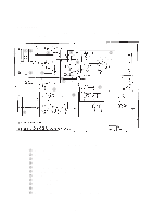
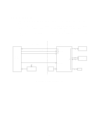
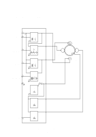
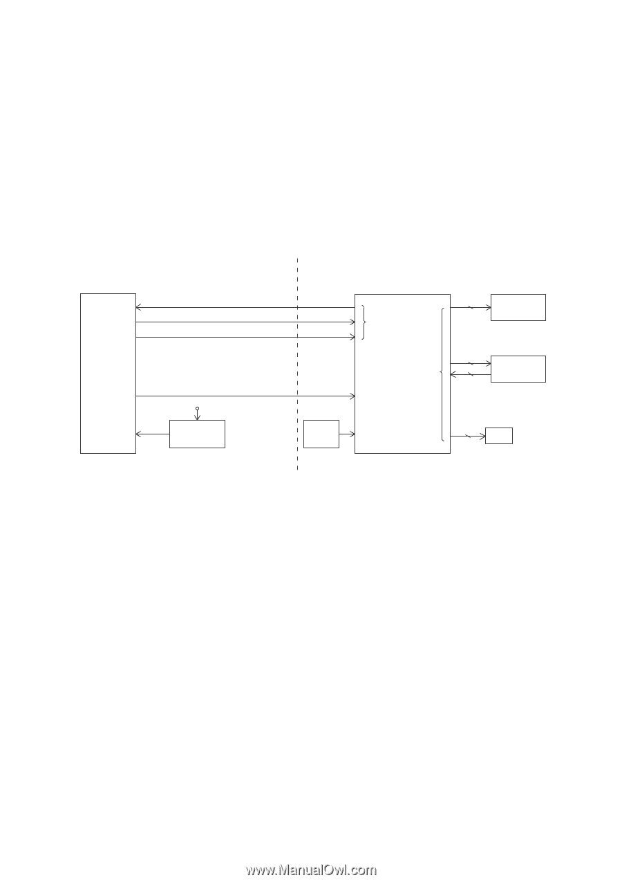
3.5 Control Panel PCB The control panel PCB and the main PCB communicate with each other by serially transmitting commands and data. The control panel unit consists of a gate array, an LCD, and LEDs, which are controlled by the gate array according to commands issued from the FAX engine on the main PCB. The calendar clock is backed up by the backup circuit on the main PCB. The panel FPC is a flexible keyboard PCB which integrates the key matrix having rubber keytops. FAX Engine Main PCB SDIN SDOUT PCLK +5V +5B Backup Circuit Control Panel PCB Serial Communications Ports Gate Array I/O Ports +5V POWER Reset Circuit RESET LCD Panel FPC (Key Matrix) LEDS Control Panel PCB and its Related Circuit III - 27
-
 1
1 -
2
-
3
-
4
-
5
-
6
-
7
-
8
-
9
-
10
-
11
-
12
-
13
-
14
-
15
-
16
-
17
-
18
-
19
-
20
-
21
-
22
-
23
-
24
-
25
-
26
-
27
-
28
-
29
-
30
-
31
-
32
-
33
-
34
-
35
-
36
-
37
-
38
-
39
-
40
-
 41
41 -
 42
42 -
 43
43 -
 44
44 -
 45
45 -
 46
46 -
 47
47 -
 48
48 -
 49
49 -
 50
50 -
 51
51 -
52
-
53
-
54
-
55
-
56
-
57
-
58
-
59
-
60
-
61
-
62
-
63
-
64
-
65
-
66
-
67
-
68
-
69
-
70
-
71
-
72
-
73
-
74
-
75
-
76
-
77
-
78
-
79
-
80
-
81
-
82
-
83
-
84
-
85
-
86
-
87
-
88
-
89
-
90
-
91
-
92
-
93
-
94
-
95
-
96
-
97
-
98
-
99
-
100
-
101
-
102
-
103
-
104
-
105
-
106
-
107
-
108
-
109
-
110
-
111
-
112
-
113
-
114
-
115
-
116
-
117
-
118
-
119
-
120
-
121
-
122
-
123
-
124
-
125
-
126
-
127
-
128
-
129
-
130
-
131
-
132
-
133
-
134
-
135
-
136
-
137
-
138
-
139
-
140
-
141
-
142
-
143
-
144
-
145
-
146
-
147
-
148
-
149
-
150
-
151
-
152
-
153
-
154
-
155
-
156
-
157
-
158
-
159
-
160
-
161
-
162
-
163
-
164
-
165
-
166
-
167
-
168
-
169
-
170
-
171
-
172
-
173
-
174
-
175
-
176
-
177
-
178
-
179
-
180
-
181
-
182
-
183
-
184
-
185
-
186
-
187
-
188
-
189
-
190
-
191
 |
 |
III –
27
3.5
Control Panel PCB
The control panel PCB and the main PCB communicate with each other by serially transmit-
ting commands and data.
The control panel unit consists of a gate array, an LCD, and LEDs, which are controlled by
the gate array according to commands issued from the FAX engine on the main PCB.
The calendar clock is backed up by the backup circuit on the main PCB.
The panel FPC is a flexible keyboard PCB which integrates the key matrix having rubber
keytops.
FAX
Engine
Backup
Circuit
+5V
Reset
Circuit
+5V
POWER
I/O Ports
Serial
Communications
Ports
RESET
+5B
LED
S
Panel FPC
(Key Matrix)
LCD
Main PCB
Control Panel PCB
SDIN
SDOUT
PCLK
Gate Array
Control Panel PCB and its Related Circuit