Brother International IntelliFax-3550 Service Manual - Page 22
Scanner Mechanism, advances with the document feed roller ASSY to the scanner
 |
View all Brother International IntelliFax-3550 manuals
Add to My Manuals
Save this manual to your list of manuals |
Page 22 highlights
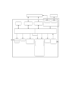
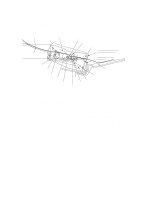
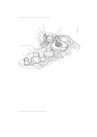
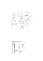
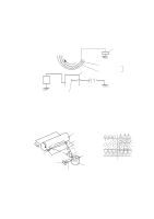
2.1 Scanner Mechanism Document ADF parts Nip-related parts Document stacker Document feed roller ASSY Document pressure bar Document ejection roller ASSY Document feeding and ejecting mechanism Document scanning mechanism 2nd mirror Document front sensor actuator Document take-in roller ASSY Separation roller ASSY Document rear sensor actuator CCD unit Lens 1st mirror LED array Document tray (Front) 2.1.1 Document feeding and ejecting mechanism This mechanism consists of the document stacker, automatic document feeder (ADF), document feed roller ASSY, and document sensors. (For details about the sensors, refer to Section 2.3.) If the operator sets documents on the document stacker and starts the scanning operation, the scanner motor rotates so that the ADF (which consists of the document take-in roller ASSY, separation roller ASSY, ADF parts and nip-related parts) feeds those documents into the equipment, starting from the bottom sheet to the top, page by page. Each document advances with the document feed roller ASSY to the scanner, and then it is fed out of the equipment with the document ejection roller ASSY. 2.1.2 Document scanning mechanism The scanner uses a charge coupled device (CCD) image sensor. As illustrated above, the LED array illuminates a document and the reflected light of the scanned image data is transmitted via the mirrors into the lens which reduces the scanned data so as to form the image on the CCD. III - 3
-
 1
1 -
2
-
3
-
4
-
5
-
6
-
7
-
8
-
9
-
10
-
11
-
12
-
13
-
14
-
15
-
16
-
 17
17 -
 18
18 -
 19
19 -
 20
20 -
 21
21 -
 22
22 -
 23
23 -
 24
24 -
 25
25 -
 26
26 -
 27
27 -
28
-
29
-
30
-
31
-
32
-
33
-
34
-
35
-
36
-
37
-
38
-
39
-
40
-
41
-
42
-
43
-
44
-
45
-
46
-
47
-
48
-
49
-
50
-
51
-
52
-
53
-
54
-
55
-
56
-
57
-
58
-
59
-
60
-
61
-
62
-
63
-
64
-
65
-
66
-
67
-
68
-
69
-
70
-
71
-
72
-
73
-
74
-
75
-
76
-
77
-
78
-
79
-
80
-
81
-
82
-
83
-
84
-
85
-
86
-
87
-
88
-
89
-
90
-
91
-
92
-
93
-
94
-
95
-
96
-
97
-
98
-
99
-
100
-
101
-
102
-
103
-
104
-
105
-
106
-
107
-
108
-
109
-
110
-
111
-
112
-
113
-
114
-
115
-
116
-
117
-
118
-
119
-
120
-
121
-
122
-
123
-
124
-
125
-
126
-
127
-
128
-
129
-
130
-
131
-
132
-
133
-
134
-
135
-
136
-
137
-
138
-
139
-
140
-
141
-
142
-
143
-
144
-
145
-
146
-
147
-
148
-
149
-
150
-
151
-
152
-
153
-
154
-
155
-
156
-
157
-
158
-
159
-
160
-
161
-
162
-
163
-
164
-
165
-
166
-
167
-
168
-
169
-
170
-
171
-
172
-
173
-
174
-
175
-
176
-
177
-
178
-
179
-
180
-
181
-
182
-
183
-
184
-
185
-
186
-
187
-
188
-
189
-
190
-
191
 |
 |
