Brother International IntelliFax-3550 Service Manual - Page 57
Panel Rear Cover and Control Panel
 |
View all Brother International IntelliFax-3550 manuals
Add to My Manuals
Save this manual to your list of manuals |
Page 57 highlights
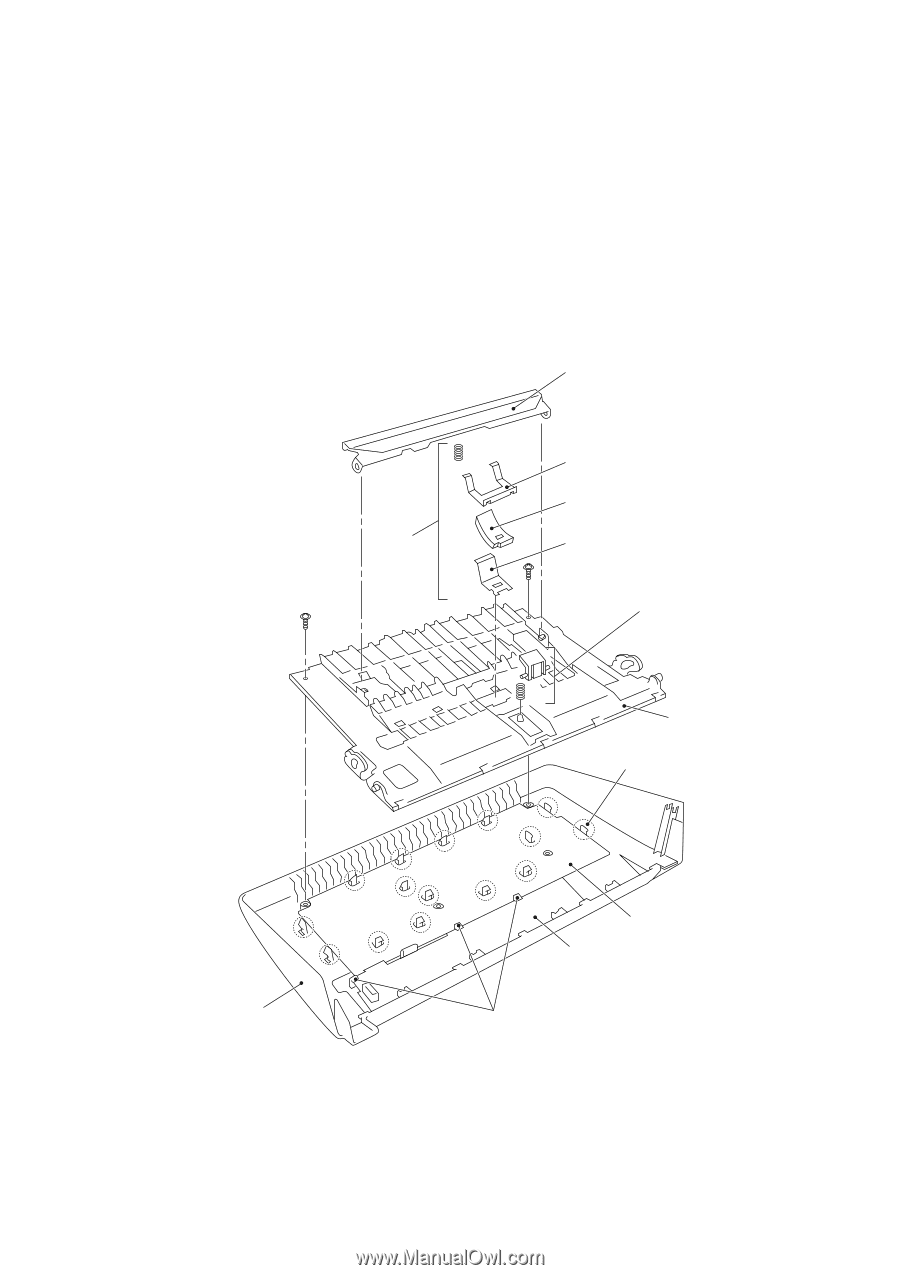
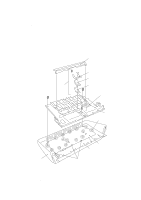
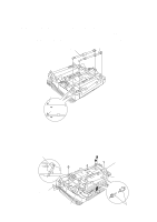
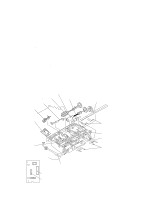
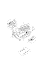
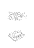
1.5 Panel Rear Cover and Control Panel (1) Place the control panel ASSY upside down. (2) Remove the document pressure bar, ADF parts, and nip-related parts from the panel rear cover. (3) Remove the two screws from the panel rear cover. (4) While lifting up the front edge of the panel rear cover, unhook it from the 15 pawls "X" provided on the control panel. (5) Unhook the control panel PCB from the three pawls "Y" on the control panel and take it out together with the FPC key. Document pressure bar ADF parts Spring plate A Separation rubber Spring plate B Nip-related parts Panel rear cover 15 "X" pawls Control panel (placed upside down) FPC key Control panel PCB 3 "Y" pawls s Reassembling Notes • When installing the spring plate B and separation rubber, align their cutouts with the boss on the panel rear cover. IV - 7
-
 1
1 -
2
-
3
-
4
-
5
-
6
-
7
-
8
-
9
-
10
-
11
-
12
-
13
-
14
-
15
-
16
-
17
-
18
-
19
-
20
-
21
-
22
-
23
-
24
-
25
-
26
-
27
-
28
-
29
-
30
-
31
-
32
-
33
-
34
-
35
-
36
-
37
-
38
-
39
-
40
-
41
-
42
-
43
-
44
-
45
-
46
-
47
-
48
-
49
-
50
-
51
-
 52
52 -
 53
53 -
 54
54 -
 55
55 -
 56
56 -
 57
57 -
 58
58 -
 59
59 -
 60
60 -
 61
61 -
 62
62 -
63
-
64
-
65
-
66
-
67
-
68
-
69
-
70
-
71
-
72
-
73
-
74
-
75
-
76
-
77
-
78
-
79
-
80
-
81
-
82
-
83
-
84
-
85
-
86
-
87
-
88
-
89
-
90
-
91
-
92
-
93
-
94
-
95
-
96
-
97
-
98
-
99
-
100
-
101
-
102
-
103
-
104
-
105
-
106
-
107
-
108
-
109
-
110
-
111
-
112
-
113
-
114
-
115
-
116
-
117
-
118
-
119
-
120
-
121
-
122
-
123
-
124
-
125
-
126
-
127
-
128
-
129
-
130
-
131
-
132
-
133
-
134
-
135
-
136
-
137
-
138
-
139
-
140
-
141
-
142
-
143
-
144
-
145
-
146
-
147
-
148
-
149
-
150
-
151
-
152
-
153
-
154
-
155
-
156
-
157
-
158
-
159
-
160
-
161
-
162
-
163
-
164
-
165
-
166
-
167
-
168
-
169
-
170
-
171
-
172
-
173
-
174
-
175
-
176
-
177
-
178
-
179
-
180
-
181
-
182
-
183
-
184
-
185
-
186
-
187
-
188
-
189
-
190
-
191
 |
 |