Brother International IntelliFax-3550 Service Manual - Page 55
Top Cover, Handset Mount and Hook Switch PCB, Side Cover
 |
View all Brother International IntelliFax-3550 manuals
Add to My Manuals
Save this manual to your list of manuals |
Page 55 highlights
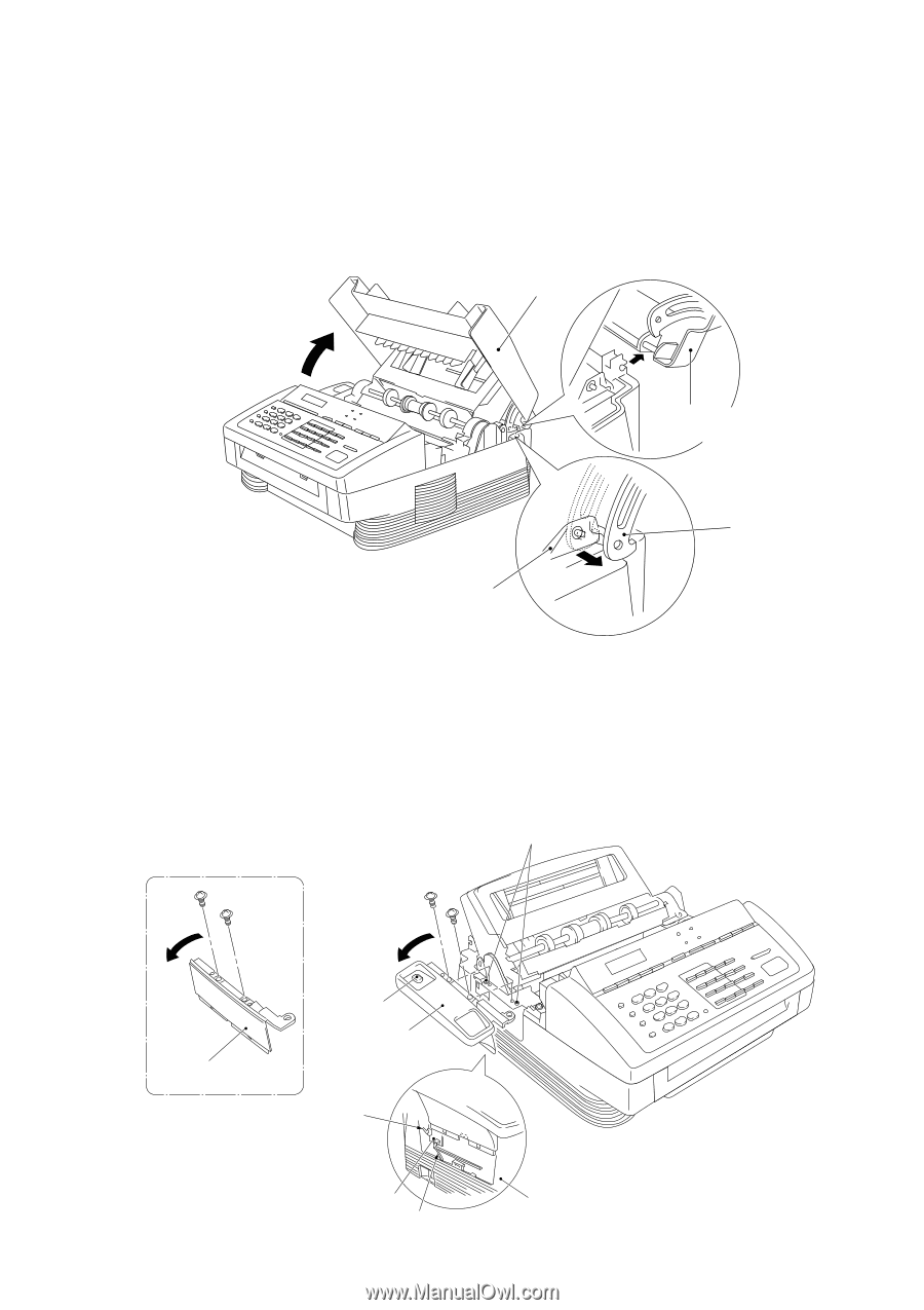
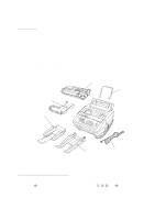
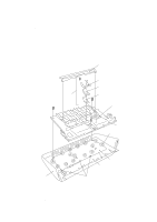
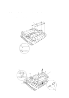
1.1 Top Cover (1) Open the top cover. (2) Push the arm of the top cover outwards with your thumb to unhook it from the main cover. (3) Turn the top cover upright and slide it to the rear. Top cover Top cover turned upright Arm Main cover 1.2 Handset Mount and Hook Switch PCB (for handset-equipped versions) Side Cover (for non-handset versions) (1) Remove the two screws from the handset mount* or the side cover.** (2) Twist the handset mount* or the side cover** so that it tilts over to the left and its upper end works out of the bosses provided on the main cover. (3) To remove the hook switch PCB*, disconnect the hook switch harness* and remove the screw. *For handset-equipped versions Bosses **For non-handset versions (Non-handset versions) (Handset-equipped versions) Side cover** Hook switch* Handset mount* Hook switch sensor* Hook switch PCB* Hook switch harness* IV - 5 Main cover
-
 1
1 -
2
-
3
-
4
-
5
-
6
-
7
-
8
-
9
-
10
-
11
-
12
-
13
-
14
-
15
-
16
-
17
-
18
-
19
-
20
-
21
-
22
-
23
-
24
-
25
-
26
-
27
-
28
-
29
-
30
-
31
-
32
-
33
-
34
-
35
-
36
-
37
-
38
-
39
-
40
-
41
-
42
-
43
-
44
-
45
-
46
-
47
-
48
-
49
-
 50
50 -
 51
51 -
 52
52 -
 53
53 -
 54
54 -
 55
55 -
 56
56 -
 57
57 -
 58
58 -
 59
59 -
 60
60 -
61
-
62
-
63
-
64
-
65
-
66
-
67
-
68
-
69
-
70
-
71
-
72
-
73
-
74
-
75
-
76
-
77
-
78
-
79
-
80
-
81
-
82
-
83
-
84
-
85
-
86
-
87
-
88
-
89
-
90
-
91
-
92
-
93
-
94
-
95
-
96
-
97
-
98
-
99
-
100
-
101
-
102
-
103
-
104
-
105
-
106
-
107
-
108
-
109
-
110
-
111
-
112
-
113
-
114
-
115
-
116
-
117
-
118
-
119
-
120
-
121
-
122
-
123
-
124
-
125
-
126
-
127
-
128
-
129
-
130
-
131
-
132
-
133
-
134
-
135
-
136
-
137
-
138
-
139
-
140
-
141
-
142
-
143
-
144
-
145
-
146
-
147
-
148
-
149
-
150
-
151
-
152
-
153
-
154
-
155
-
156
-
157
-
158
-
159
-
160
-
161
-
162
-
163
-
164
-
165
-
166
-
167
-
168
-
169
-
170
-
171
-
172
-
173
-
174
-
175
-
176
-
177
-
178
-
179
-
180
-
181
-
182
-
183
-
184
-
185
-
186
-
187
-
188
-
189
-
190
-
191
 |
 |