Brother International IntelliFax-3550 Service Manual - Page 60
Scanner Frame ASSY, Pressure roller ASSY.
 |
View all Brother International IntelliFax-3550 manuals
Add to My Manuals
Save this manual to your list of manuals |
Page 60 highlights
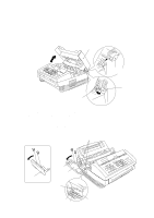
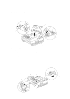
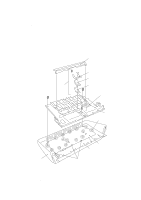
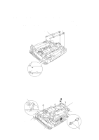
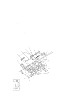
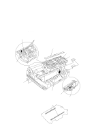
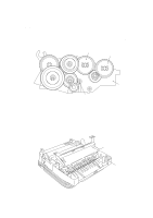
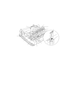
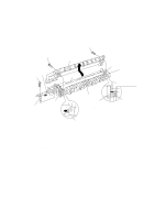
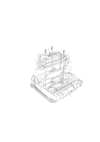
1.8 Scanner Frame ASSY (1) You can remove the following parts from the top of the scanner frame ASSY without taking out the ASSY from the main cover: • Cover glass. Turn the cover glass up towards you. • Ejection leaf springs. Remove them while slightly pulling up the front edges. • Document take-in roller ASSY. Unhook the latch of the gear, take it off, and lift up the ASSY. • Separation roller ASSY. First unhook the latch of the adjacent gear and take it off, and then remove the separation roller ASSY in the same way as for the document take-in roller ASSY. • Pressure roller ASSY. While pressing down the leaf springs, remove the ASSY. • Bar lens and LED array. • Document front sensor actuator. • Document rear sensor actuator. While pressing down the leaf spring and pulling the boss "X" provided on the scanner frame ASSY to the front, slightly move the actuator to the left and lift it up. • Document sensor PCB. Disconnect the CCD harness and LED array harness from the document sensor PCB. Take the main-sensor harness out of the three clamps (see the illustration on the next page) and then disconnect it from the PCB. Document take-in roller ASSY Document rear sensor actuator Document front sensor actuator Separation roller ASSY Pressure roller ASSY Cover glass Document sensor PCB Leaf springs Boss "X" PC1 CCD harness P2 P1 PC2 P3 Main-sensor harness connector CCD harness connector PC1: Document front sensor PC2: Document rear sensor IV - 10 (Front) Bar lens and LED array CCD unit (Do not remove) Ejection leaf springs
-
 1
1 -
2
-
3
-
4
-
5
-
6
-
7
-
8
-
9
-
10
-
11
-
12
-
13
-
14
-
15
-
16
-
17
-
18
-
19
-
20
-
21
-
22
-
23
-
24
-
25
-
26
-
27
-
28
-
29
-
30
-
31
-
32
-
33
-
34
-
35
-
36
-
37
-
38
-
39
-
40
-
41
-
42
-
43
-
44
-
45
-
46
-
47
-
48
-
49
-
50
-
51
-
52
-
53
-
54
-
 55
55 -
 56
56 -
 57
57 -
 58
58 -
 59
59 -
 60
60 -
 61
61 -
 62
62 -
 63
63 -
 64
64 -
 65
65 -
66
-
67
-
68
-
69
-
70
-
71
-
72
-
73
-
74
-
75
-
76
-
77
-
78
-
79
-
80
-
81
-
82
-
83
-
84
-
85
-
86
-
87
-
88
-
89
-
90
-
91
-
92
-
93
-
94
-
95
-
96
-
97
-
98
-
99
-
100
-
101
-
102
-
103
-
104
-
105
-
106
-
107
-
108
-
109
-
110
-
111
-
112
-
113
-
114
-
115
-
116
-
117
-
118
-
119
-
120
-
121
-
122
-
123
-
124
-
125
-
126
-
127
-
128
-
129
-
130
-
131
-
132
-
133
-
134
-
135
-
136
-
137
-
138
-
139
-
140
-
141
-
142
-
143
-
144
-
145
-
146
-
147
-
148
-
149
-
150
-
151
-
152
-
153
-
154
-
155
-
156
-
157
-
158
-
159
-
160
-
161
-
162
-
163
-
164
-
165
-
166
-
167
-
168
-
169
-
170
-
171
-
172
-
173
-
174
-
175
-
176
-
177
-
178
-
179
-
180
-
181
-
182
-
183
-
184
-
185
-
186
-
187
-
188
-
189
-
190
-
191
 |
 |
