Brother International IntelliFax-3550 Service Manual - Page 85
IMPORTANT, The LCD clears the current display. - instructions
 |
View all Brother International IntelliFax-3550 manuals
Add to My Manuals
Save this manual to your list of manuals |
Page 85 highlights
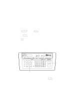
IMPORTANT Basically, the maintenance-mode functions listed on the previous page should be accessed by service personnel only. However, you may allow end users to access some of these under the guidance of service personnel (e.g., by telephone). The user-accessible functions (codes 10, 11, 82, and 91) are shaded in the above table. Function code 10 accesses the firmware switches WSW01 to WSW34, each of which has eight selectors. You should not allow end users to access all of those selectors, but you may allow them to access user-accessible selectors which are shaded in the firmware switch tables in Subsection 3.6. The service personnel should instruct end users to follow the procedure given below. (1) Press the Function key and the Mode key in this order. The LCD clears the current display. NOTE: The Mode key is inoperable during standby for redialing, timer, paging, and forwarding. (2) Press the 0 key. (3) Enter the desired function code (10, 11, 82, or 91) with the numerical keys. For function code 10, access the desired firmware switch according to the operating procedure described in Subsection 3.6. Function key Mode key MFC 7550MC status status Set Function Clear Hook ABC DEF 123 Hold GH I JKL MNO 4 56 Redial / Pause PQRS TUV W X YZ 789 Speed Dial 0 Voice Fax status Fine Fax Photo S.Fine F/ T Tel-index Resolution Mode SIX IN ONE FAX PRINTER COPIER SCANNER PC FAX MESSAGE CENTER Coverpage Super Q.Scan Help L Speaker H 01 02 03 13 14 15 04 05 06 16 17 18 07 08 09 19 20 21 10 11 12 Shift 22 23 24 On/Off Line Photo FF/Cont Sort Test/ Enlarge/ Reset Reduce Print Priority Copy Record Erase Play Stop Start Stop key 0 key (4) To make the equipment return to the standby state, press the Stop key V - 3
-
 1
1 -
2
-
3
-
4
-
5
-
6
-
7
-
8
-
9
-
10
-
11
-
12
-
13
-
14
-
15
-
16
-
17
-
18
-
19
-
20
-
21
-
22
-
23
-
24
-
25
-
26
-
27
-
28
-
29
-
30
-
31
-
32
-
33
-
34
-
35
-
36
-
37
-
38
-
39
-
40
-
41
-
42
-
43
-
44
-
45
-
46
-
47
-
48
-
49
-
50
-
51
-
52
-
53
-
54
-
55
-
56
-
57
-
58
-
59
-
60
-
61
-
62
-
63
-
64
-
65
-
66
-
67
-
68
-
69
-
70
-
71
-
72
-
73
-
74
-
75
-
76
-
77
-
78
-
79
-
 80
80 -
 81
81 -
 82
82 -
 83
83 -
 84
84 -
 85
85 -
 86
86 -
 87
87 -
 88
88 -
 89
89 -
 90
90 -
91
-
92
-
93
-
94
-
95
-
96
-
97
-
98
-
99
-
100
-
101
-
102
-
103
-
104
-
105
-
106
-
107
-
108
-
109
-
110
-
111
-
112
-
113
-
114
-
115
-
116
-
117
-
118
-
119
-
120
-
121
-
122
-
123
-
124
-
125
-
126
-
127
-
128
-
129
-
130
-
131
-
132
-
133
-
134
-
135
-
136
-
137
-
138
-
139
-
140
-
141
-
142
-
143
-
144
-
145
-
146
-
147
-
148
-
149
-
150
-
151
-
152
-
153
-
154
-
155
-
156
-
157
-
158
-
159
-
160
-
161
-
162
-
163
-
164
-
165
-
166
-
167
-
168
-
169
-
170
-
171
-
172
-
173
-
174
-
175
-
176
-
177
-
178
-
179
-
180
-
181
-
182
-
183
-
184
-
185
-
186
-
187
-
188
-
189
-
190
-
191
 |
 |
