Brother International IntelliFax-3550 Service Manual - Page 73
Gear Drive Unit, Remove the three screws and take out the gear drive unit.
 |
View all Brother International IntelliFax-3550 manuals
Add to My Manuals
Save this manual to your list of manuals |
Page 73 highlights
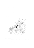
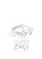
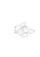
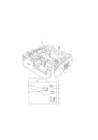
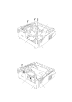
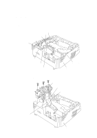
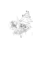
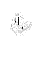
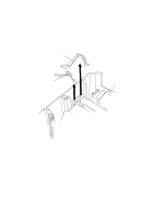
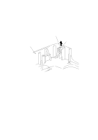
1.18 Gear Drive Unit (1) Take out the heater harness (blue and brown wires) from the clamps provided on the gear drive unit. (2) Take out the main motor harness, solenoid harness, and drum grounding harness from the clamp provided on the main cover. Heater harness (blue and brown wires) Solenoid harness Drum grounding harness Gear drive unit Main motor Main motor harness Clamp provided on the main cover (Rear) Relay PCB Main cover (placed upside down) (3) Remove the three screws and take out the gear drive unit. Gear drive unit Drum grounding harness (from the high-voltage power supply PCB) Solenoid harness (from the main PCB) Main motor harness (from the main PCB) (Rear) IV - 23 Main cover (placed upside down)
-
 1
1 -
2
-
3
-
4
-
5
-
6
-
7
-
8
-
9
-
10
-
11
-
12
-
13
-
14
-
15
-
16
-
17
-
18
-
19
-
20
-
21
-
22
-
23
-
24
-
25
-
26
-
27
-
28
-
29
-
30
-
31
-
32
-
33
-
34
-
35
-
36
-
37
-
38
-
39
-
40
-
41
-
42
-
43
-
44
-
45
-
46
-
47
-
48
-
49
-
50
-
51
-
52
-
53
-
54
-
55
-
56
-
57
-
58
-
59
-
60
-
61
-
62
-
63
-
64
-
65
-
66
-
67
-
 68
68 -
 69
69 -
 70
70 -
 71
71 -
 72
72 -
 73
73 -
 74
74 -
 75
75 -
 76
76 -
 77
77 -
 78
78 -
79
-
80
-
81
-
82
-
83
-
84
-
85
-
86
-
87
-
88
-
89
-
90
-
91
-
92
-
93
-
94
-
95
-
96
-
97
-
98
-
99
-
100
-
101
-
102
-
103
-
104
-
105
-
106
-
107
-
108
-
109
-
110
-
111
-
112
-
113
-
114
-
115
-
116
-
117
-
118
-
119
-
120
-
121
-
122
-
123
-
124
-
125
-
126
-
127
-
128
-
129
-
130
-
131
-
132
-
133
-
134
-
135
-
136
-
137
-
138
-
139
-
140
-
141
-
142
-
143
-
144
-
145
-
146
-
147
-
148
-
149
-
150
-
151
-
152
-
153
-
154
-
155
-
156
-
157
-
158
-
159
-
160
-
161
-
162
-
163
-
164
-
165
-
166
-
167
-
168
-
169
-
170
-
171
-
172
-
173
-
174
-
175
-
176
-
177
-
178
-
179
-
180
-
181
-
182
-
183
-
184
-
185
-
186
-
187
-
188
-
189
-
190
-
191
 |
 |

IV –
23
1.18
Gear Drive Unit
(1)
Take out the heater harness (blue and brown wires) from the clamps provided on the
gear drive unit.
(2)
Take out the main motor harness, solenoid harness, and drum grounding harness from
the clamp provided on the main cover.
Relay PCB
Main cover (placed upside
down)
(Rear)
Clamp provided on the main cover
Main motor harness
Drum grounding harness
Heater harness
(blue and brown wires)
Solenoid harness
Gear drive unit
Main motor
(3)
Remove the three screws and take out the gear drive unit.
(Rear)
Gear drive unit
Solenoid harness (from the main PCB)
Drum grounding harness (from the
high-voltage power supply PCB)
Main cover (placed upside
down)
Main motor harness
(from the main PCB)