Brother International IntelliFax-3550 Service Manual - Page 84
List Of Maintenance-mode Functions
 |
View all Brother International IntelliFax-3550 manuals
Add to My Manuals
Save this manual to your list of manuals |
Page 84 highlights
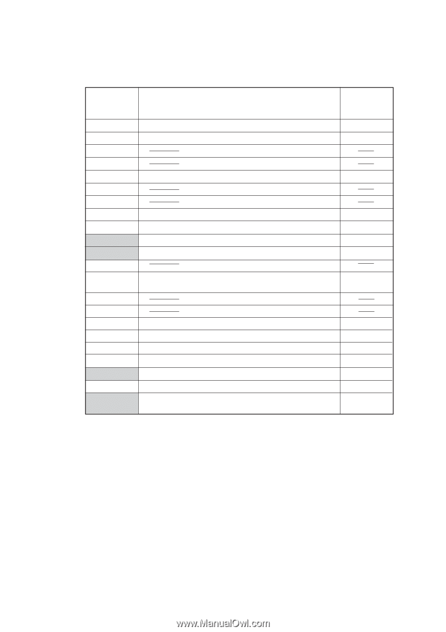
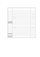
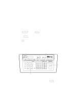
2. LIST OF MAINTENANCE-MODE FUNCTIONS Function Code 01 02 03 04 05 06 07 08 09 10 11 12 13 14 15 Maintenance-mode Functions Function E2PROM Parameter Initialization Scanning Compensation Data Initialization Printout of Scanning Compensation Data ADF* Performance Test Test Pattern 1 Firmware Switch Setting Printout of Firmware Switch Data Operational Check of Control Panel PCB (Check of Keys and Buttons) Reference Subsection (Page) 3.1 (V-4) 3.2 (V-5) 3.3 (V-6) 3.4 (V-8) 3.5 (V-9) 3.6 (V-10) 3.6 (V-46) 3.7 (V-47) 32 Sensor Operational Check 55 CCD Scanner Area Setting 82 Equipment Error Code Indication 87 Output of Transmission Log to the Line 91 E2PROM Parameter Initialization (except the tele- phone number storage area) 3.8 (V-48) 3.9 (V-49) 3.10 (V-49) 3.11 (V-50) 3.1 (V-4) * ADF: Automatic document feeder V - 2
-
 1
1 -
2
-
3
-
4
-
5
-
6
-
7
-
8
-
9
-
10
-
11
-
12
-
13
-
14
-
15
-
16
-
17
-
18
-
19
-
20
-
21
-
22
-
23
-
24
-
25
-
26
-
27
-
28
-
29
-
30
-
31
-
32
-
33
-
34
-
35
-
36
-
37
-
38
-
39
-
40
-
41
-
42
-
43
-
44
-
45
-
46
-
47
-
48
-
49
-
50
-
51
-
52
-
53
-
54
-
55
-
56
-
57
-
58
-
59
-
60
-
61
-
62
-
63
-
64
-
65
-
66
-
67
-
68
-
69
-
70
-
71
-
72
-
73
-
74
-
75
-
76
-
77
-
78
-
 79
79 -
 80
80 -
 81
81 -
 82
82 -
 83
83 -
 84
84 -
 85
85 -
 86
86 -
 87
87 -
 88
88 -
 89
89 -
90
-
91
-
92
-
93
-
94
-
95
-
96
-
97
-
98
-
99
-
100
-
101
-
102
-
103
-
104
-
105
-
106
-
107
-
108
-
109
-
110
-
111
-
112
-
113
-
114
-
115
-
116
-
117
-
118
-
119
-
120
-
121
-
122
-
123
-
124
-
125
-
126
-
127
-
128
-
129
-
130
-
131
-
132
-
133
-
134
-
135
-
136
-
137
-
138
-
139
-
140
-
141
-
142
-
143
-
144
-
145
-
146
-
147
-
148
-
149
-
150
-
151
-
152
-
153
-
154
-
155
-
156
-
157
-
158
-
159
-
160
-
161
-
162
-
163
-
164
-
165
-
166
-
167
-
168
-
169
-
170
-
171
-
172
-
173
-
174
-
175
-
176
-
177
-
178
-
179
-
180
-
181
-
182
-
183
-
184
-
185
-
186
-
187
-
188
-
189
-
190
-
191
 |
 |