Brother International IntelliFax-3550 Service Manual - Page 68
High-voltage Power Supply PCB and Fan 1, for any toner particles, paper dust or dirt
 |
View all Brother International IntelliFax-3550 manuals
Add to My Manuals
Save this manual to your list of manuals |
Page 68 highlights
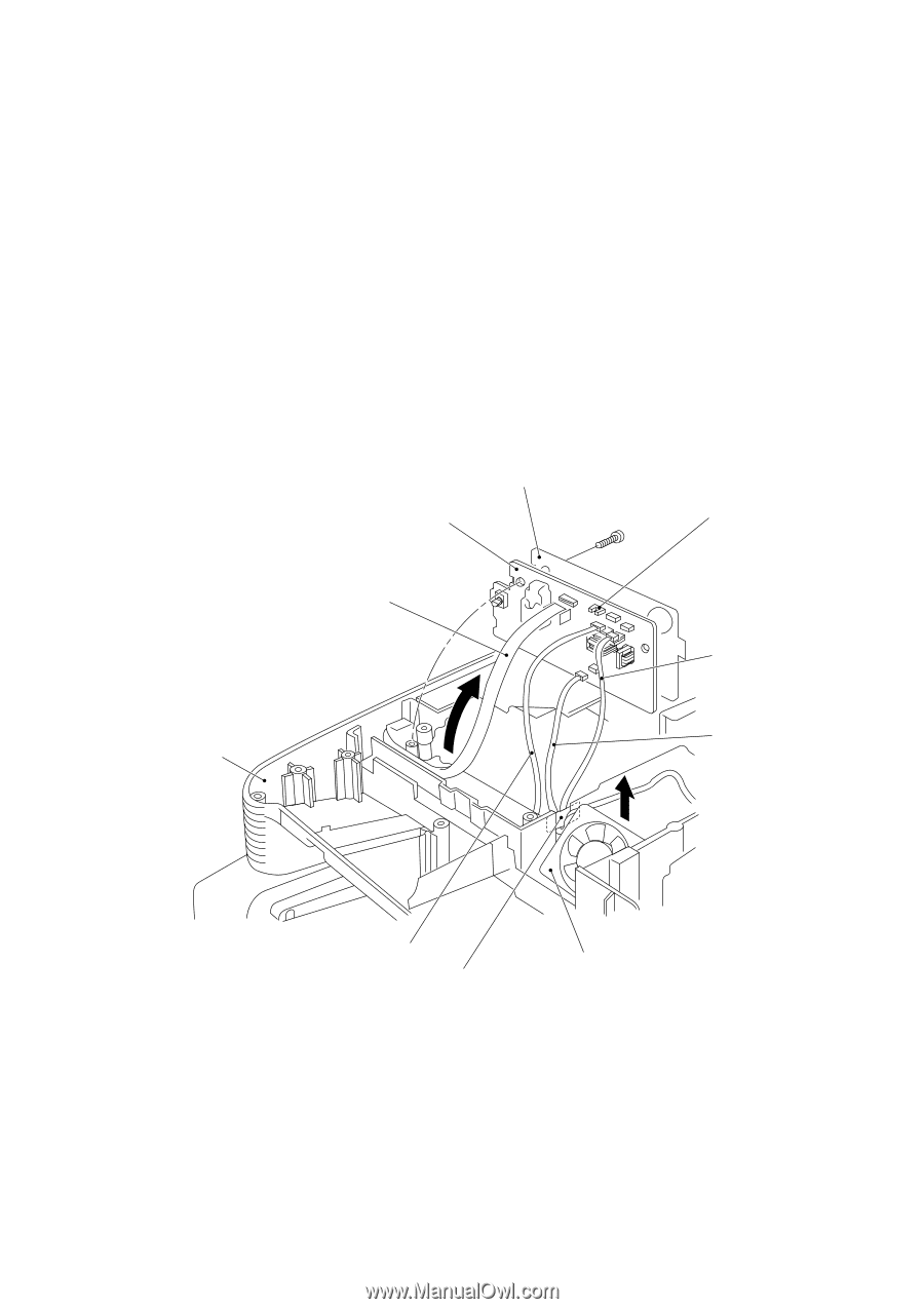
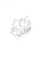
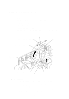
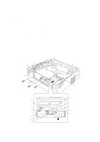
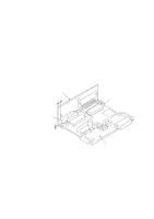
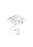
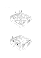
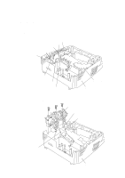
1.14 High-voltage Power Supply PCB and Fan 1 (1) Remove the screw and the insulation film. (2) While pressing down the high-voltage power supply PCB, slightly shift it to the front of the machine. (3) Slightly lift up the high-voltage power supply PCB and disconnect the following four things: • Relay-high-voltage flat cable (12-pin) • Eraser harness (4-pin) • Fan harness (3-pin) • Drum grounding harness (2-pin) NOTE: The fan harness and the drum grounding harness pass through the slot below the fan motor film. (4) Take out the fan 1. Insulation film High-voltage power supply PCB Paper ejection sensor Relay-high-voltage flat cable Fan harness Main cover (placed upside down) Drum grounding harness (Front) Eraser harness Fan motor film Fan 1 s Reassembling Notes • Before reinstalling the high-voltage power supply PCB, check the high-voltage contacts for any toner particles, paper dust or dirt, and clean them out. • When reassembling the above parts, make sure that the harnesses are routed on the main cover as illustrated in Section 1.23. • Once the fan motor film is removed, you are recommended to use a new film. • When setting the fan 1, be careful with the installation direction. The name plate should be face-up (when the equipment is placed upside down). IV - 18
-
 1
1 -
2
-
3
-
4
-
5
-
6
-
7
-
8
-
9
-
10
-
11
-
12
-
13
-
14
-
15
-
16
-
17
-
18
-
19
-
20
-
21
-
22
-
23
-
24
-
25
-
26
-
27
-
28
-
29
-
30
-
31
-
32
-
33
-
34
-
35
-
36
-
37
-
38
-
39
-
40
-
41
-
42
-
43
-
44
-
45
-
46
-
47
-
48
-
49
-
50
-
51
-
52
-
53
-
54
-
55
-
56
-
57
-
58
-
59
-
60
-
61
-
62
-
 63
63 -
 64
64 -
 65
65 -
 66
66 -
 67
67 -
 68
68 -
 69
69 -
 70
70 -
 71
71 -
 72
72 -
 73
73 -
74
-
75
-
76
-
77
-
78
-
79
-
80
-
81
-
82
-
83
-
84
-
85
-
86
-
87
-
88
-
89
-
90
-
91
-
92
-
93
-
94
-
95
-
96
-
97
-
98
-
99
-
100
-
101
-
102
-
103
-
104
-
105
-
106
-
107
-
108
-
109
-
110
-
111
-
112
-
113
-
114
-
115
-
116
-
117
-
118
-
119
-
120
-
121
-
122
-
123
-
124
-
125
-
126
-
127
-
128
-
129
-
130
-
131
-
132
-
133
-
134
-
135
-
136
-
137
-
138
-
139
-
140
-
141
-
142
-
143
-
144
-
145
-
146
-
147
-
148
-
149
-
150
-
151
-
152
-
153
-
154
-
155
-
156
-
157
-
158
-
159
-
160
-
161
-
162
-
163
-
164
-
165
-
166
-
167
-
168
-
169
-
170
-
171
-
172
-
173
-
174
-
175
-
176
-
177
-
178
-
179
-
180
-
181
-
182
-
183
-
184
-
185
-
186
-
187
-
188
-
189
-
190
-
191
 |
 |