Brother International IntelliFax-3550 Service Manual - Page 29
Sensors and Actuators
 |
View all Brother International IntelliFax-3550 manuals
Add to My Manuals
Save this manual to your list of manuals |
Page 29 highlights
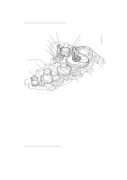
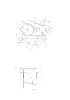
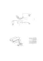
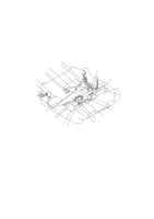
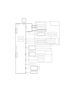
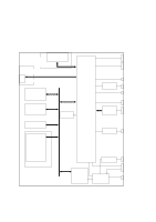
2.3 Sensors and Actuators This equipment has ten sensors: two microswitches, six photosensors and two thermisters as described below. Sensor name Hook switch sensor Cover sensor Registration sensor Sheet feeder cover sensor Paper ejection sensor Document front sensor Document rear sensor Toner sensor Toner thermister Heater thermister Type Microswitch Microswitch Photosensor (PC1) Photosensor (PC2) Photosensor (PC1) Photosensor (PC1) Photosensor (PC2) Photosensor (PH1) P1 __ Located on Hook switch PCB Relay PCB Relay PCB Relay PCB High-voltage power supply PCB Document sensor PCB Document sensor PCB Toner sensor PCB (on the laser unit) Toner sensor PCB (on the laser unit) Fixing unit • Hook switch sensor which detects whether the handset is placed on the handset mount. • Cover sensor which detects whether the top cover is closed. • Registration sensor which detects the leading and trailing edges of paper, which allows the controller to determine the registration timing and check paper jam. • Sheet feeder cover sensor which detects whether the sheet feeder cover is closed. • Paper ejection sensor which detects whether the recording paper goes out of the equip- ment. • Document front sensor which detects the presence of documents. • Document rear sensor which detects the leading and trailing edges of pages to tell the control circuitry when the leading edge of a new page has reached the starting position and when the scan for that page is over. • Toner sensor which detects whether there is toner or a toner cartridge is loaded. • Toner thermister which detects the temperature of the toner cartridge. • Heater thermister which detects the temperature of the heater roller of the fixing unit. These photosensors are a photointerrupter consisting of a light-emitting diode and a lightsensitive transistor. Each of them has an actuator separately arranged as shown on the next page. III - 10
-
 1
1 -
2
-
3
-
4
-
5
-
6
-
7
-
8
-
9
-
10
-
11
-
12
-
13
-
14
-
15
-
16
-
17
-
18
-
19
-
20
-
21
-
22
-
23
-
 24
24 -
 25
25 -
 26
26 -
 27
27 -
 28
28 -
 29
29 -
 30
30 -
 31
31 -
 32
32 -
 33
33 -
 34
34 -
35
-
36
-
37
-
38
-
39
-
40
-
41
-
42
-
43
-
44
-
45
-
46
-
47
-
48
-
49
-
50
-
51
-
52
-
53
-
54
-
55
-
56
-
57
-
58
-
59
-
60
-
61
-
62
-
63
-
64
-
65
-
66
-
67
-
68
-
69
-
70
-
71
-
72
-
73
-
74
-
75
-
76
-
77
-
78
-
79
-
80
-
81
-
82
-
83
-
84
-
85
-
86
-
87
-
88
-
89
-
90
-
91
-
92
-
93
-
94
-
95
-
96
-
97
-
98
-
99
-
100
-
101
-
102
-
103
-
104
-
105
-
106
-
107
-
108
-
109
-
110
-
111
-
112
-
113
-
114
-
115
-
116
-
117
-
118
-
119
-
120
-
121
-
122
-
123
-
124
-
125
-
126
-
127
-
128
-
129
-
130
-
131
-
132
-
133
-
134
-
135
-
136
-
137
-
138
-
139
-
140
-
141
-
142
-
143
-
144
-
145
-
146
-
147
-
148
-
149
-
150
-
151
-
152
-
153
-
154
-
155
-
156
-
157
-
158
-
159
-
160
-
161
-
162
-
163
-
164
-
165
-
166
-
167
-
168
-
169
-
170
-
171
-
172
-
173
-
174
-
175
-
176
-
177
-
178
-
179
-
180
-
181
-
182
-
183
-
184
-
185
-
186
-
187
-
188
-
189
-
190
-
191
 |
 |
