Brother International IntelliFax-3550 Service Manual - Page 53
Preparation, How to Access the Object Component, in this case.
 |
View all Brother International IntelliFax-3550 manuals
Add to My Manuals
Save this manual to your list of manuals |
Page 53 highlights
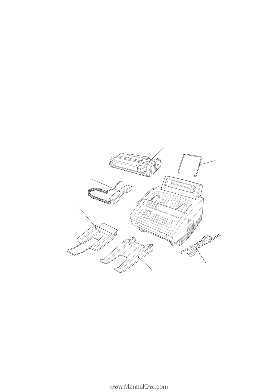
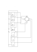
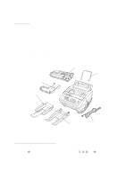
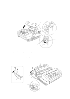
s Preparation Prior to proceeding to the disassembly procedure, (1) Unplug - the modular jack of the telephone line, - the modular jack of the curled cord (and remove the handset), and - the modular jack of an external telephone set if mounted. (Not shown below.) (2) Remove - the wire extension, - the document tray, - the paper tray, and - the drum unit (with the toner cartridge loaded). Handset and curled cord Drum unit (with toner cartridge loaded) Wire extension Document tray Paper tray Telephone line cord s How to Access the Object Component • On the next page is a disassembly order flow which helps you access the object component. To remove the relay PCB, for example, first find it on the flow and learn its number (F in this case). You should remove parts numbered 1, 3, B, and E so as to access the relay PCB. • Unless otherwise specified, the disassembled parts or components should be reassembled in the reverse order of removal. IV - 3
-
 1
1 -
2
-
3
-
4
-
5
-
6
-
7
-
8
-
9
-
10
-
11
-
12
-
13
-
14
-
15
-
16
-
17
-
18
-
19
-
20
-
21
-
22
-
23
-
24
-
25
-
26
-
27
-
28
-
29
-
30
-
31
-
32
-
33
-
34
-
35
-
36
-
37
-
38
-
39
-
40
-
41
-
42
-
43
-
44
-
45
-
46
-
47
-
 48
48 -
 49
49 -
 50
50 -
 51
51 -
 52
52 -
 53
53 -
 54
54 -
 55
55 -
 56
56 -
 57
57 -
 58
58 -
59
-
60
-
61
-
62
-
63
-
64
-
65
-
66
-
67
-
68
-
69
-
70
-
71
-
72
-
73
-
74
-
75
-
76
-
77
-
78
-
79
-
80
-
81
-
82
-
83
-
84
-
85
-
86
-
87
-
88
-
89
-
90
-
91
-
92
-
93
-
94
-
95
-
96
-
97
-
98
-
99
-
100
-
101
-
102
-
103
-
104
-
105
-
106
-
107
-
108
-
109
-
110
-
111
-
112
-
113
-
114
-
115
-
116
-
117
-
118
-
119
-
120
-
121
-
122
-
123
-
124
-
125
-
126
-
127
-
128
-
129
-
130
-
131
-
132
-
133
-
134
-
135
-
136
-
137
-
138
-
139
-
140
-
141
-
142
-
143
-
144
-
145
-
146
-
147
-
148
-
149
-
150
-
151
-
152
-
153
-
154
-
155
-
156
-
157
-
158
-
159
-
160
-
161
-
162
-
163
-
164
-
165
-
166
-
167
-
168
-
169
-
170
-
171
-
172
-
173
-
174
-
175
-
176
-
177
-
178
-
179
-
180
-
181
-
182
-
183
-
184
-
185
-
186
-
187
-
188
-
189
-
190
-
191
 |
 |