Brother International IntelliFax-3550 Service Manual - Page 69
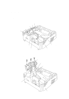
Solenoid harness 2-pin, P8, Main-panel harness 5-pin, P5
 |
View all Brother International IntelliFax-3550 manuals
Add to My Manuals
Save this manual to your list of manuals |
Page 69 highlights
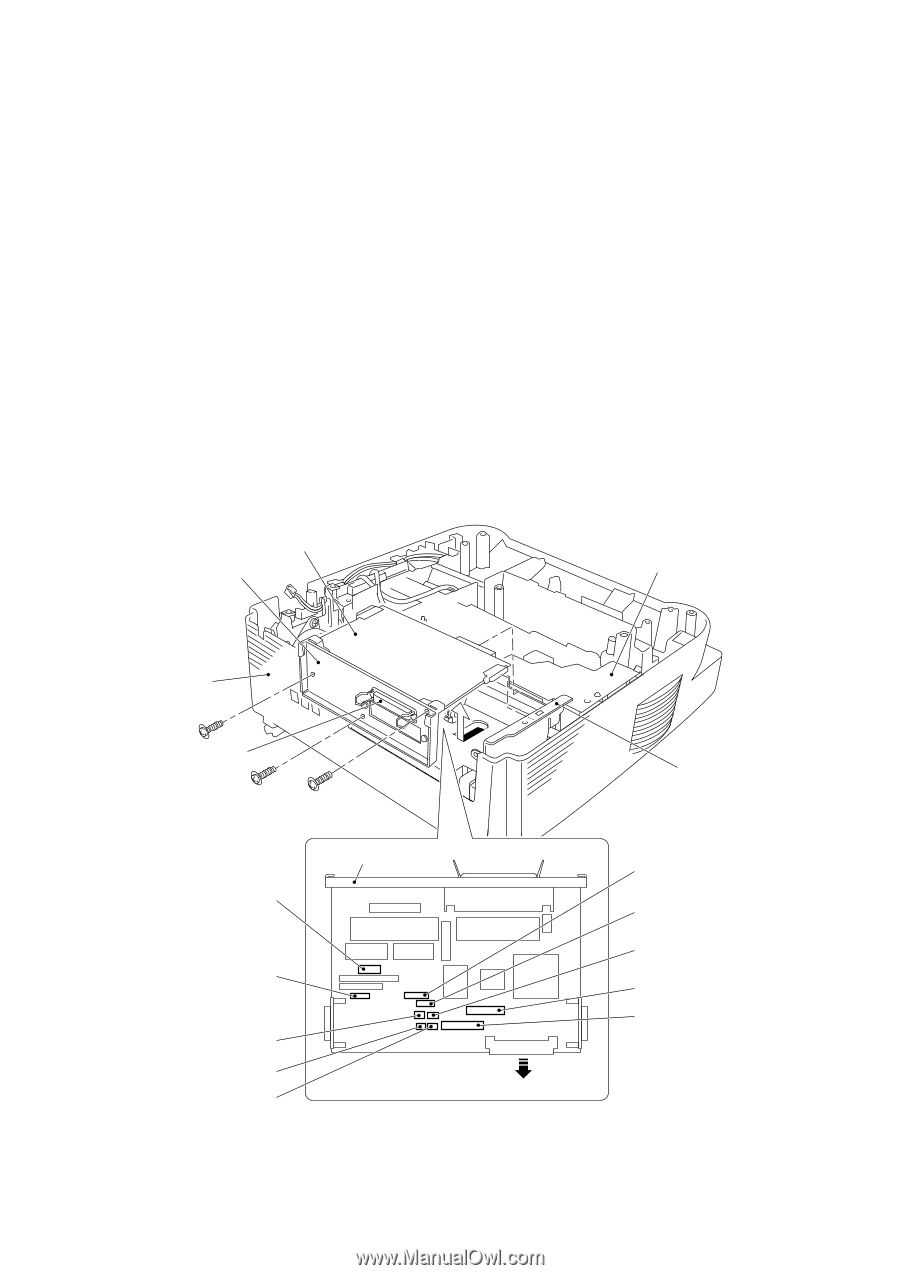
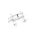
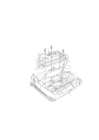
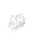
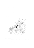
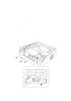
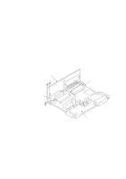
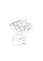
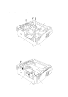
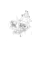
1.15 Main PCB (1) Remove the three screws from the interface plate. (2) Pull out the interface plate to the rear of the machine and take out the main PCB from the shield bracket. (3) Slightly lift up the main PCB and disconnect the following ten harnesses: • Main motor harness (4-pin), P9 • Scanner motor harness (6-pin), P10 • Main-low-voltage harness (5-pin), P7 • Main-panel harness (5-pin), P5 • Solenoid harness (2-pin), P8 • Fan 2 harness (2-pin), P18 • Speaker harness (2-pin), P16 • Hook switch harness (2-pin), P11 • Main-NCU harness (12-pin), P6 Main-NCU harness (6-pin), P6 (on the European and Asian versions only) • Main-sensor harness (11-pin), P4 Main PCB Interface plate Relay PCB Main cover (placed upside down) Centronics parallel interface connector (Rear) Main motor harness Scanner motor harness Solenoid harness Speaker harness Hook switch harness Interface plate P9 P7 P10 P5 P8 P18 P4 P16 P11 P6 P13 Relay PCB Shield bracket Main-low-voltage harness Main-panel harness Fan 2 harness Main-sensor harness Main-NCU harness IV - 19
-
 1
1 -
2
-
3
-
4
-
5
-
6
-
7
-
8
-
9
-
10
-
11
-
12
-
13
-
14
-
15
-
16
-
17
-
18
-
19
-
20
-
21
-
22
-
23
-
24
-
25
-
26
-
27
-
28
-
29
-
30
-
31
-
32
-
33
-
34
-
35
-
36
-
37
-
38
-
39
-
40
-
41
-
42
-
43
-
44
-
45
-
46
-
47
-
48
-
49
-
50
-
51
-
52
-
53
-
54
-
55
-
56
-
57
-
58
-
59
-
60
-
61
-
62
-
63
-
 64
64 -
 65
65 -
 66
66 -
 67
67 -
 68
68 -
 69
69 -
 70
70 -
 71
71 -
 72
72 -
 73
73 -
 74
74 -
75
-
76
-
77
-
78
-
79
-
80
-
81
-
82
-
83
-
84
-
85
-
86
-
87
-
88
-
89
-
90
-
91
-
92
-
93
-
94
-
95
-
96
-
97
-
98
-
99
-
100
-
101
-
102
-
103
-
104
-
105
-
106
-
107
-
108
-
109
-
110
-
111
-
112
-
113
-
114
-
115
-
116
-
117
-
118
-
119
-
120
-
121
-
122
-
123
-
124
-
125
-
126
-
127
-
128
-
129
-
130
-
131
-
132
-
133
-
134
-
135
-
136
-
137
-
138
-
139
-
140
-
141
-
142
-
143
-
144
-
145
-
146
-
147
-
148
-
149
-
150
-
151
-
152
-
153
-
154
-
155
-
156
-
157
-
158
-
159
-
160
-
161
-
162
-
163
-
164
-
165
-
166
-
167
-
168
-
169
-
170
-
171
-
172
-
173
-
174
-
175
-
176
-
177
-
178
-
179
-
180
-
181
-
182
-
183
-
184
-
185
-
186
-
187
-
188
-
189
-
190
-
191
 |
 |