Brother International IntelliFax-3550 Service Manual - Page 52
Tightening Torque List, Taptite, cup B M3x6
 |
View all Brother International IntelliFax-3550 manuals
Add to My Manuals
Save this manual to your list of manuals |
Page 52 highlights
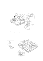
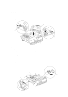
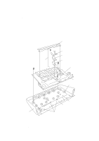
Tightening Torque List Location Handset mount Hook switch PCB Panel rear cover Inner cover Scanner motor Fixing unit Laser unit Toner sensor PCB Bottom plate (On the main shield bracket) (On the gear drive unit) Grounding wire Low-voltage power supply PCB High-voltage power supply PCB Interface plate Relay PCB Shield bracket NCU PCB ASSY Drive unit Screw type Taptite, cup B M3x10 Taptite, cup B M3x6 Taptite, cup B M3x8 Taptite, cup B 4x12 Taptite, cup B 3x10 Screw, pan (washer) 3x8DB Taptite, bind B 4x12 Taptite, bind B 3x10 Taptite, bind B 4x12 Taptite, cup B 3x8 Taptite, cup B 4x12 Taptite, cup S 3x6 Taptite, cup S 3x6 Screw, pan (washer) 4x8DB Taptite, bind 4x12 Taptite, bind 4x12 Taptite, bind 3x6 Taptite, bind B 4x12 Taptite, cup B 3x10 Taptite, cup B 3x10 Taptite, cup B 4x20 Taptite, bind B 4x12 Q'ty Tightening torque (kgf•cm) 2 5 ±1 1 5 ±1 2 3 ±1 2 8 ±1 3 8 ±1 1 7 ±2 1 10 ±1 2 8 ±1 3 8 ±1 1 6 ±1 5 8 ±1 2 5 ±1 2 8 ±1 1 7 ±2 1 10 ±1 1 10 ±1 3 5 ±1 1 10 ±1 3 5 ±1 1 5 ±1 3 12 ±1 1 10 ±1 IV - 2
-
 1
1 -
2
-
3
-
4
-
5
-
6
-
7
-
8
-
9
-
10
-
11
-
12
-
13
-
14
-
15
-
16
-
17
-
18
-
19
-
20
-
21
-
22
-
23
-
24
-
25
-
26
-
27
-
28
-
29
-
30
-
31
-
32
-
33
-
34
-
35
-
36
-
37
-
38
-
39
-
40
-
41
-
42
-
43
-
44
-
45
-
46
-
 47
47 -
 48
48 -
 49
49 -
 50
50 -
 51
51 -
 52
52 -
 53
53 -
 54
54 -
 55
55 -
 56
56 -
 57
57 -
58
-
59
-
60
-
61
-
62
-
63
-
64
-
65
-
66
-
67
-
68
-
69
-
70
-
71
-
72
-
73
-
74
-
75
-
76
-
77
-
78
-
79
-
80
-
81
-
82
-
83
-
84
-
85
-
86
-
87
-
88
-
89
-
90
-
91
-
92
-
93
-
94
-
95
-
96
-
97
-
98
-
99
-
100
-
101
-
102
-
103
-
104
-
105
-
106
-
107
-
108
-
109
-
110
-
111
-
112
-
113
-
114
-
115
-
116
-
117
-
118
-
119
-
120
-
121
-
122
-
123
-
124
-
125
-
126
-
127
-
128
-
129
-
130
-
131
-
132
-
133
-
134
-
135
-
136
-
137
-
138
-
139
-
140
-
141
-
142
-
143
-
144
-
145
-
146
-
147
-
148
-
149
-
150
-
151
-
152
-
153
-
154
-
155
-
156
-
157
-
158
-
159
-
160
-
161
-
162
-
163
-
164
-
165
-
166
-
167
-
168
-
169
-
170
-
171
-
172
-
173
-
174
-
175
-
176
-
177
-
178
-
179
-
180
-
181
-
182
-
183
-
184
-
185
-
186
-
187
-
188
-
189
-
190
-
191
 |
 |
