Creative 70EM896106000 Owners Manual - Page 22
Front Panel Connections, Preamp S/PDIF Digital Audio Input & Output
 |
UPC - 054651126893
View all Creative 70EM896106000 manuals
Add to My Manuals
Save this manual to your list of manuals |
Page 22 highlights
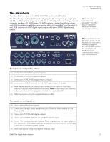
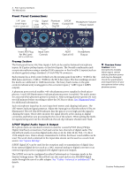
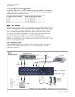
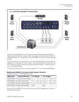
3 - PCIe Card & Interfaces The MicroDock Front Panel Connections Preamp Section The front panel mono Mic/Line inputs A & B can be used as balanced microphone inputs, hi-Z guitar pickup inputs, or line level inputs. The Neutrik combination jack accepts microphones using a standard XLR connector or line level/hi-Z inputs (such as an electric guitar) using a standard 1/4 inch TRS/TS connector. Each preamp has a level control which sets the preamp gain from 0dB to +65dB for the XLR input and from -15dB to +50dB for the Hi-Z line input. The line markings around the knobs are calibrated in 10dB increments. The heavy hash marks on the gain controls indicate unity analog gain to the converter inputs (~5dBV input = 0dBFS output). A phantom power switch enables +48 volt phantom power supplied to both microphones. A red LED illuminates to indicate phantom power is enabled. The audio mutes for a second when phantom power is turned on. After turning phantom power off, wait two full minutes before recording to allow the DC bias to drain. See "Phantom Power" for additional information. Each microphone input has its own input level meters and clipping indicators. The LED meters indicate signal presence. Adjust the input gain so that the yellow LEDs are illuminated. The red Clip LED indicates that the gain is set too high and the signal is clipping the input. These LEDs monitor the signal directly at the analog-to-digital converters and before any processing by the rest of the system. When setting the levels for signals being sent into the MicroDock, the red clip indicator should never flash. S/PDIF Digital Audio Input & Output RCA phono jacks are standard connectors used for coaxial S/PDIF (Sony/Philips Digital InterFace) connections. Each jack carries two channels of digital audio. The MicroDock sends or receives digital audio data at 44.1k, 48k, 88.2k, 96k, 176.4k or 192k sample rates. Data is always transmitted at 24-bits, but lower word widths can be read. The word clock contained in the input data stream can be used as a word clock source. See "System Settings". S/PDIF digital I/O can be used for the reception and/ or transmission of digital data from external digital devices such as a DAT, external analog-to-digital converter or an external signal processor equipped with digital inputs and outputs. The S/PDIF out can be configured in either Professional or Consumer mode in the Session Settings menu. The MicroDock can also send and receive AES/EBU digital audio through the use of a cable adapter. See "Cables - balanced or unbalanced?" for details. 22 Phantom Power Caution: Some microphones (notably ribbon types) cannot tolerate phantom power and may be damaged. Check the specifications and requirements of your microphone before using phantom power. Creative Professional
-
 1
1 -
2
-
3
-
4
-
5
-
6
-
7
-
8
-
9
-
10
-
11
-
12
-
13
-
14
-
15
-
16
-
 17
17 -
 18
18 -
 19
19 -
 20
20 -
 21
21 -
 22
22 -
 23
23 -
 24
24 -
 25
25 -
 26
26 -
 27
27 -
28
-
29
-
30
-
31
-
32
-
33
-
34
-
35
-
36
-
37
-
38
-
39
-
40
-
41
-
42
-
43
-
44
-
45
-
46
-
47
-
48
-
49
-
50
-
51
-
52
-
53
-
54
-
55
-
56
-
57
-
58
-
59
-
60
-
61
-
62
-
63
-
64
-
65
-
66
-
67
-
68
-
69
-
70
-
71
-
72
-
73
-
74
-
75
-
76
-
77
-
78
-
79
-
80
-
81
-
82
-
83
-
84
-
85
-
86
-
87
-
88
-
89
-
90
-
91
-
92
-
93
-
94
-
95
-
96
-
97
-
98
-
99
-
100
-
101
-
102
-
103
-
104
-
105
-
106
-
107
-
108
-
109
-
110
-
111
-
112
-
113
-
114
-
115
-
116
-
117
-
118
-
119
-
120
-
121
-
122
-
123
-
124
-
125
-
126
-
127
-
128
-
129
-
130
-
131
-
132
 |
 |
