Creative 70EM896106000 Owners Manual - Page 52
Input, Output, Physical Output, Host Output
 |
UPC - 054651126893
View all Creative 70EM896106000 manuals
Add to My Manuals
Save this manual to your list of manuals |
Page 52 highlights
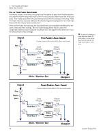
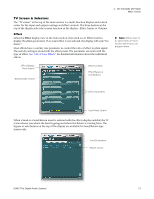
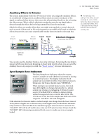
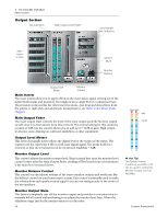
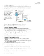
4 - The PatchMix DSP Mixer Main Section Input Selecting the Input display view shows a graphic representation of the PatchMix DSP Mixer inputs. This screen is only a display, unlike the Effects and Outputs screens, which allow you to make routing changes. Input routing changes are made by adding mixer strips. See "Mixer Strip Creation". The input routings are divided into two categories: Physical Inputs and Host Inputs. Select either category by clicking on the Physical or Host button. Physical Input Display Host Input Display The Input and Output displays make it much easier to understand the signal routings of a complex mixer setup. Tip: Clicking on any of the input routings in the TV display highlights the corresponding mixer strip. Output Selecting the Output display view shows a graphic representation of the PatchMix DSP Mixer outputs. The output routings are divided into two categories: Physical Outputs and Host Outputs. Select either category by clicking on the Physical or Host button. Physical Output Display Host Output Display The Host Output display shows all the Insert Routings in addition to the Main Mix and Monitor out routings. Click on the desired row to make or break a physical output connection. The Physical Output screen displays and allows you to connect the Main and Monitor outputs of the mixer to "physical" analog or digital outputs. Click on the box in the mix or monitor area to make (or break) a connection. The Host Output screen displays and allows you to view the Host (ASIO or WAVE) outputs of the mixer. See "Insert Section" for information on how to connect the inserts. 52 Creative Professional
-
 1
1 -
2
-
3
-
4
-
5
-
6
-
7
-
8
-
9
-
10
-
11
-
12
-
13
-
14
-
15
-
16
-
17
-
18
-
19
-
20
-
21
-
22
-
23
-
24
-
25
-
26
-
27
-
28
-
29
-
30
-
31
-
32
-
33
-
34
-
35
-
36
-
37
-
38
-
39
-
40
-
41
-
42
-
43
-
44
-
45
-
46
-
 47
47 -
 48
48 -
 49
49 -
 50
50 -
 51
51 -
 52
52 -
 53
53 -
 54
54 -
 55
55 -
 56
56 -
 57
57 -
58
-
59
-
60
-
61
-
62
-
63
-
64
-
65
-
66
-
67
-
68
-
69
-
70
-
71
-
72
-
73
-
74
-
75
-
76
-
77
-
78
-
79
-
80
-
81
-
82
-
83
-
84
-
85
-
86
-
87
-
88
-
89
-
90
-
91
-
92
-
93
-
94
-
95
-
96
-
97
-
98
-
99
-
100
-
101
-
102
-
103
-
104
-
105
-
106
-
107
-
108
-
109
-
110
-
111
-
112
-
113
-
114
-
115
-
116
-
117
-
118
-
119
-
120
-
121
-
122
-
123
-
124
-
125
-
126
-
127
-
128
-
129
-
130
-
131
-
132
 |
 |
