Creative 70EM896106000 Owners Manual - Page 30
Mixer Window, Mixer Block Diagram, Pre Fader or Post Fader, Input, Monitor - windows 8
 |
UPC - 054651126893
View all Creative 70EM896106000 manuals
Add to My Manuals
Save this manual to your list of manuals |
Page 30 highlights
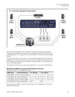
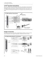
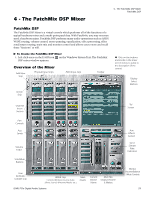
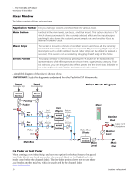
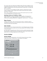
4 - The PatchMix DSP Mixer Overview of the Mixer Mixer Window The Mixer consists of four main sections. Application Toolbar Lets you manage sessions and show/hide the various views. Main Section Controls all the main levels, aux buses, and their inserts. This section also has a "TV" which shows parameters for the currently selected effect and the input/output patching. It also shows the session's current sample rate and whether it's set to internal or external clock. Mixer Strips This section is located to the left of the Main Section and shows all the currently instantiated mixer strips. Mixer strips can represent Physical analog/digital inputs, or Host inputs such as ASIO or Direct Sound. Mixer strips can be added or deleted as necessary. This section can be resized by dragging the left edge of the frame. Effects Palette This popup window is invoked by pressing the FX button in the toolbar. Iconic representations of all effects presets are shown here, organized by category. From this window, you can drag and drop effect presets into the insert slots available on the mixer strips and main section aux buses and main inserts. A simplified diagram of the mixer is shown below. IMPORTANT: Study this diagram to understand how the PatchMix DSP Mixer works. Input Post-Fader Strip Input Pre-Fader Strip Mixer Block Diagram Insert Section Insert Section Panning Fader MUTE Aux 1 Aux Bus 1 Aux 1 Send Amount Aux 2 Aux Bus 2 Fader MUTE Aux 2 Send Amount Aux Effects Insert Section Insert Section Return Amount Return Amount Main Bus Meter Main Bus Effects Insert Section Main Level Monitor Out MUTE Output 1L/1R & Headphones Monitor Level Main Out Pre Fader or Post Fader When creating a new Mixer Strip, you have the option for the Aux Sends to be placed Post Fader (both Aux Sends come after the channel fader) or Pre Fader (both Aux Sends come before the channel fader). The Pre-fader option allows you to use either Aux Send as another mix bus, which is unaffected by the channel fader. More Information. 30 Creative Professional
-
 1
1 -
2
-
3
-
4
-
5
-
6
-
7
-
8
-
9
-
10
-
11
-
12
-
13
-
14
-
15
-
16
-
17
-
18
-
19
-
20
-
21
-
22
-
23
-
24
-
 25
25 -
 26
26 -
 27
27 -
 28
28 -
 29
29 -
 30
30 -
 31
31 -
 32
32 -
 33
33 -
 34
34 -
 35
35 -
36
-
37
-
38
-
39
-
40
-
41
-
42
-
43
-
44
-
45
-
46
-
47
-
48
-
49
-
50
-
51
-
52
-
53
-
54
-
55
-
56
-
57
-
58
-
59
-
60
-
61
-
62
-
63
-
64
-
65
-
66
-
67
-
68
-
69
-
70
-
71
-
72
-
73
-
74
-
75
-
76
-
77
-
78
-
79
-
80
-
81
-
82
-
83
-
84
-
85
-
86
-
87
-
88
-
89
-
90
-
91
-
92
-
93
-
94
-
95
-
96
-
97
-
98
-
99
-
100
-
101
-
102
-
103
-
104
-
105
-
106
-
107
-
108
-
109
-
110
-
111
-
112
-
113
-
114
-
115
-
116
-
117
-
118
-
119
-
120
-
121
-
122
-
123
-
124
-
125
-
126
-
127
-
128
-
129
-
130
-
131
-
132
 |
 |