Creative 70EM896106000 Owners Manual - Page 50
Main by clicking on the insert, the screen shows the available parameters for the currently
 |
UPC - 054651126893
View all Creative 70EM896106000 manuals
Add to My Manuals
Save this manual to your list of manuals |
Page 50 highlights
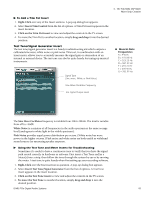
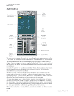
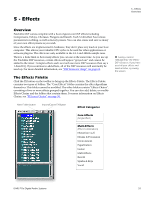
4 - The PatchMix DSP Mixer Main Section Main Section Physical/Host Select Buttons View Selection Buttons "TV" Screen Master Aux Send Amounts Aux Insert Section Master Aux Return Amounts Main Insert Section Sync & Sample Rate Indicators Monitor Controls Output Fader & Meters Session Name The main section contains all controls for controlling the main mix elements as well as a "TV screen" for viewing the input/output routing or parameters of the selected insert. The three buttons across the top of the main section select what is shown on the TV display. Input and output routings are graphically displayed. When an insert is selected (by clicking on the insert), the screen shows the available parameters for the currently selected insert. Below the TV screen is the Aux Bus section where effects, effects chains or other inserts can be assigned to the two aux buses. Send and return levels can be individually controlled for each of the two Aux Buses. The Aux 1 and Aux 2 buses are fed by the two Aux Sends on each mixer strip. The Master Send Level control on Aux bus 1 and 2 can be used to attenuate or boost the signal going into the Auxiliary Inserts. There is also a Master Return Level to control the amount of the effected signal that will be returned into the main mix. The Main Bus can also have a chain of effects inserted. (You might put an EQ here to equalize your entire mix or add an ASIO or WAVE send to record the mix.) Note that the Main Output level control comes before the Monitor Level so that you can control the monitor level without affecting the level of your recording mix or main mix. There is a stereo peak meter that indicates the signal strength for the main mix. The Monitor section has a volume, balance, and a mute control to cut off the monitor output. 50 Creative Professional
-
 1
1 -
2
-
3
-
4
-
5
-
6
-
7
-
8
-
9
-
10
-
11
-
12
-
13
-
14
-
15
-
16
-
17
-
18
-
19
-
20
-
21
-
22
-
23
-
24
-
25
-
26
-
27
-
28
-
29
-
30
-
31
-
32
-
33
-
34
-
35
-
36
-
37
-
38
-
39
-
40
-
41
-
42
-
43
-
44
-
 45
45 -
 46
46 -
 47
47 -
 48
48 -
 49
49 -
 50
50 -
 51
51 -
 52
52 -
 53
53 -
 54
54 -
 55
55 -
56
-
57
-
58
-
59
-
60
-
61
-
62
-
63
-
64
-
65
-
66
-
67
-
68
-
69
-
70
-
71
-
72
-
73
-
74
-
75
-
76
-
77
-
78
-
79
-
80
-
81
-
82
-
83
-
84
-
85
-
86
-
87
-
88
-
89
-
90
-
91
-
92
-
93
-
94
-
95
-
96
-
97
-
98
-
99
-
100
-
101
-
102
-
103
-
104
-
105
-
106
-
107
-
108
-
109
-
110
-
111
-
112
-
113
-
114
-
115
-
116
-
117
-
118
-
119
-
120
-
121
-
122
-
123
-
124
-
125
-
126
-
127
-
128
-
129
-
130
-
131
-
132
 |
 |
