Creative 70EM896106000 Owners Manual - Page 83
Level Meter, Gain Reduction Meter, being attenuated as the Gate shuts off.
 |
UPC - 054651126893
View all Creative 70EM896106000 manuals
Add to My Manuals
Save this manual to your list of manuals |
Page 83 highlights
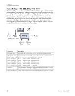
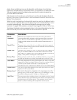
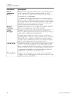
Level Meter This meter represents the input signal level in dB, and is in fact the output of the Gate's envelope follower. Since the envelope follower is driven by the greater of the left or right channel, this monophonic meter represents the greater of the two input signals. Gain Reduction Meter This meter shows the value in dB of the gate control signal which is used to boost or attenuate the input signal. Its most-rightward maximum value of 0dB represents a unity gain path through the Gate in its turn-on state. Except for the possibility of the 1 millisecond lookahead latency, the Gate behaves exactly as a straight wire in this turned-on state. Values less than 0dB represent the amount by which the input signal is being attenuated as the Gate shuts off. The most-leftward gain shutoff value achieved by the Gain meter is set by the Max Gain Reduction parameter (values from -70dB to -infinity are off the meter.) The speed with which the Gain signal decays from 0dB to the shutoff value can be observed to change according to the Release time parameter. 5 - Effects Core Effects Descriptions E-MU PCIe Digital Audio Systems 83
-
 1
1 -
2
-
3
-
4
-
5
-
6
-
7
-
8
-
9
-
10
-
11
-
12
-
13
-
14
-
15
-
16
-
17
-
18
-
19
-
20
-
21
-
22
-
23
-
24
-
25
-
26
-
27
-
28
-
29
-
30
-
31
-
32
-
33
-
34
-
35
-
36
-
37
-
38
-
39
-
40
-
41
-
42
-
43
-
44
-
45
-
46
-
47
-
48
-
49
-
50
-
51
-
52
-
53
-
54
-
55
-
56
-
57
-
58
-
59
-
60
-
61
-
62
-
63
-
64
-
65
-
66
-
67
-
68
-
69
-
70
-
71
-
72
-
73
-
74
-
75
-
76
-
77
-
 78
78 -
 79
79 -
 80
80 -
 81
81 -
 82
82 -
 83
83 -
 84
84 -
 85
85 -
 86
86 -
 87
87 -
 88
88 -
89
-
90
-
91
-
92
-
93
-
94
-
95
-
96
-
97
-
98
-
99
-
100
-
101
-
102
-
103
-
104
-
105
-
106
-
107
-
108
-
109
-
110
-
111
-
112
-
113
-
114
-
115
-
116
-
117
-
118
-
119
-
120
-
121
-
122
-
123
-
124
-
125
-
126
-
127
-
128
-
129
-
130
-
131
-
132
 |
 |
