Creative 70EM896106000 Owners Manual - Page 42
Meter Inserts, Right-Click, Insert ASIO Direct Monitor, Choose one of the Send Outputs., Cancel
 |
UPC - 054651126893
View all Creative 70EM896106000 manuals
Add to My Manuals
Save this manual to your list of manuals |
Page 42 highlights
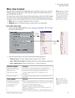
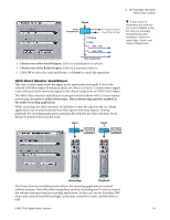
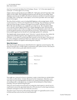
4 - The PatchMix DSP Mixer Mixer Strip Creation To Add an ASIO Direct Monitor Send/Return: 1. Right-Click over the Insert section. A pop-up dialog box appears. 2. Select Insert ASIO Direct Monitor from the list of options. The following dialog box appears. 3. Choose one of the Send Outputs. Click on a destination to select it. 4. Choose one of the Return Inputs. Click on a source to select it. 5. Click OK to select the Send and Return, or Cancel to cancel the operation. Meter Inserts Keeping track of signal levels is important in any audio system, be it analog or digital. You want to keep the signal levels running as close to maximum in order to achieve high resolution and low noise. On the other hand, you don't want the signal level so high as to cause clipping. To help you maintain optimum signal levels, we have included Peak Level Meters, which can be dropped into any insert location. The insert meters are of the "peak hold" type. The topmost bar in the meter holds its highest level for a second to let you see transients that would otherwise be too quick for the eye. The peak meters are also color-coded to indicate the signal strength. The chart below outlines the meanings of the colors. Avoid lighting the topmost red bar, as this indicates distortion of the signal. Click on the clip indicator to turn it off. Meter Color Indicates Red Indicates signal clipping. Yellow Good strong signal level. Green Signal is present. One of the most obvious uses of the insert meters is to set input levels. On the analog inputs, the analog-to-digital converter (ADC) is one of the most critical points in the signal path. You want the input signal level to drive the 24-bit ADCs into their optimum range without clipping. A reading of 0dB on an input meter indicates signal clipping. Level 70 60 50 40 30 20 10 --12dB Each bar of the meter equals 1dB. The yellow bars begin at -12dB below full scale. 42 Creative Professional
-
 1
1 -
2
-
3
-
4
-
5
-
6
-
7
-
8
-
9
-
10
-
11
-
12
-
13
-
14
-
15
-
16
-
17
-
18
-
19
-
20
-
21
-
22
-
23
-
24
-
25
-
26
-
27
-
28
-
29
-
30
-
31
-
32
-
33
-
34
-
35
-
36
-
 37
37 -
 38
38 -
 39
39 -
 40
40 -
 41
41 -
 42
42 -
 43
43 -
 44
44 -
 45
45 -
 46
46 -
 47
47 -
48
-
49
-
50
-
51
-
52
-
53
-
54
-
55
-
56
-
57
-
58
-
59
-
60
-
61
-
62
-
63
-
64
-
65
-
66
-
67
-
68
-
69
-
70
-
71
-
72
-
73
-
74
-
75
-
76
-
77
-
78
-
79
-
80
-
81
-
82
-
83
-
84
-
85
-
86
-
87
-
88
-
89
-
90
-
91
-
92
-
93
-
94
-
95
-
96
-
97
-
98
-
99
-
100
-
101
-
102
-
103
-
104
-
105
-
106
-
107
-
108
-
109
-
110
-
111
-
112
-
113
-
114
-
115
-
116
-
117
-
118
-
119
-
120
-
121
-
122
-
123
-
124
-
125
-
126
-
127
-
128
-
129
-
130
-
131
-
132
 |
 |
