Creative 70EM896106000 Owners Manual - Page 71
Flanger, Feedback, Delay
 |
UPC - 054651126893
View all Creative 70EM896106000 manuals
Add to My Manuals
Save this manual to your list of manuals |
Page 71 highlights
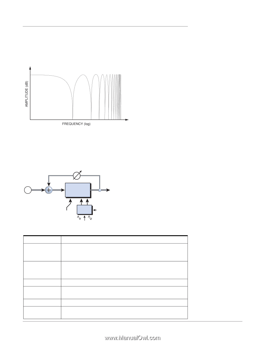
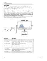
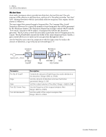
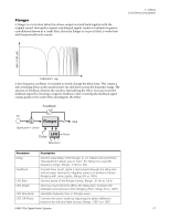
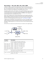
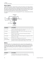
Flanger A flanger is a very short delay line whose output is mixed back together with the original sound. Mixing the original and delayed signals results in multiple frequency cancellations known as a comb filter. Since the flanger is a type of filter, it works best with harmonically rich sounds. 5 - Effects Core Effects Descriptions A low frequency oscillator is included to slowly change the delay time. This creates a rich, sweeping effect as the notches move up and down across the frequency range. The amount of feedback deepens the notches, intensifying the effect. You can invert the feedback signal by choosing a negative feedback value. Inverting the feedback signal creates peaks in the notch filter and deepens the effect. Feedback In Flanger Out Signal path = Stereo LFO Phase Delay Waveform Parameter Delay Feedback LFO Rate LFO Depth LFO Waveform LFO L/R Phase Description Sets the initial delay of the flanger in .01 millisecond increments. This parameter allows you to "tune" the flanger to a specific frequency range. Range: .01ms to 4ms Controls how much signal is recirculated through the delay line and increases resonance. Negative values can produce intense flanging with some signals. Range 0% to 100% Sets the speed of the flanger sweep. Range: .01 Hz to 10Hz Sets how much the LFO affects the delay time. Increases the animation and amount of the flanging effect. Range 05 to 100% Selectable between Sine or Triangle wave. Controls the stereo width by adjusting the phase difference between the left and right sweeps. Range: -180° to +180° E-MU PCIe Digital Audio Systems 71
-
 1
1 -
2
-
3
-
4
-
5
-
6
-
7
-
8
-
9
-
10
-
11
-
12
-
13
-
14
-
15
-
16
-
17
-
18
-
19
-
20
-
21
-
22
-
23
-
24
-
25
-
26
-
27
-
28
-
29
-
30
-
31
-
32
-
33
-
34
-
35
-
36
-
37
-
38
-
39
-
40
-
41
-
42
-
43
-
44
-
45
-
46
-
47
-
48
-
49
-
50
-
51
-
52
-
53
-
54
-
55
-
56
-
57
-
58
-
59
-
60
-
61
-
62
-
63
-
64
-
65
-
 66
66 -
 67
67 -
 68
68 -
 69
69 -
 70
70 -
 71
71 -
 72
72 -
 73
73 -
 74
74 -
 75
75 -
 76
76 -
77
-
78
-
79
-
80
-
81
-
82
-
83
-
84
-
85
-
86
-
87
-
88
-
89
-
90
-
91
-
92
-
93
-
94
-
95
-
96
-
97
-
98
-
99
-
100
-
101
-
102
-
103
-
104
-
105
-
106
-
107
-
108
-
109
-
110
-
111
-
112
-
113
-
114
-
115
-
116
-
117
-
118
-
119
-
120
-
121
-
122
-
123
-
124
-
125
-
126
-
127
-
128
-
129
-
130
-
131
-
132
 |
 |