Kyocera FS-1128MFP Service Manual - Page 160
(2) Detaching and refitting the retard roller assembly, retard guide.
 |
View all Kyocera FS-1128MFP manuals
Add to My Manuals
Save this manual to your list of manuals |
Page 160 highlights
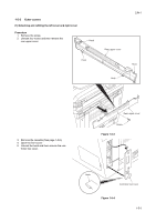
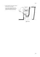
2JN (2) Detaching and refitting the retard roller assembly Procedure 1. Remove the cassette (See page 1-5-6). 2. Push the bottom plate down until it locks. 3. Unhook two hooks and then remove the retard guide. Retard guide Hook Cassestte Hook Bottom plate 4. Remove the retard roller assembly. Cassette Retard guide Hook Hook Figure 1-5-10 1-5-8 ᕃ Retard roller Assembly ᕄ Figure 1-5-11
-
 1
1 -
2
-
3
-
4
-
5
-
6
-
7
-
8
-
9
-
10
-
11
-
12
-
13
-
14
-
15
-
16
-
17
-
18
-
19
-
20
-
21
-
22
-
23
-
24
-
25
-
26
-
27
-
28
-
29
-
30
-
31
-
32
-
33
-
34
-
35
-
36
-
37
-
38
-
39
-
40
-
41
-
42
-
43
-
44
-
45
-
46
-
47
-
48
-
49
-
50
-
51
-
52
-
53
-
54
-
55
-
56
-
57
-
58
-
59
-
60
-
61
-
62
-
63
-
64
-
65
-
66
-
67
-
68
-
69
-
70
-
71
-
72
-
73
-
74
-
75
-
76
-
77
-
78
-
79
-
80
-
81
-
82
-
83
-
84
-
85
-
86
-
87
-
88
-
89
-
90
-
91
-
92
-
93
-
94
-
95
-
96
-
97
-
98
-
99
-
100
-
101
-
102
-
103
-
104
-
105
-
106
-
107
-
108
-
109
-
110
-
111
-
112
-
113
-
114
-
115
-
116
-
117
-
118
-
119
-
120
-
121
-
122
-
123
-
124
-
125
-
126
-
127
-
128
-
129
-
130
-
131
-
132
-
133
-
134
-
135
-
136
-
137
-
138
-
139
-
140
-
141
-
142
-
143
-
144
-
145
-
146
-
147
-
148
-
149
-
150
-
151
-
152
-
153
-
154
-
 155
155 -
 156
156 -
 157
157 -
 158
158 -
 159
159 -
 160
160 -
 161
161 -
 162
162 -
 163
163 -
 164
164 -
 165
165 -
166
-
167
-
168
-
169
-
170
-
171
-
172
-
173
-
174
-
175
-
176
-
177
-
178
-
179
-
180
-
181
-
182
-
183
-
184
-
185
-
186
-
187
-
188
-
189
-
190
-
191
-
192
-
193
-
194
-
195
-
196
-
197
-
198
-
199
-
200
-
201
-
202
-
203
-
204
-
205
-
206
-
207
-
208
-
209
-
210
-
211
-
212
-
213
-
214
-
215
-
216
-
217
-
218
-
219
-
220
-
221
-
222
-
223
-
224
-
225
-
226
-
227
-
228
-
229
-
230
-
231
-
232
-
233
-
234
-
235
-
236
-
237
-
238
-
239
-
240
-
241
-
242
-
243
-
244
-
245
-
246
-
247
-
248
-
249
-
250
-
251
-
252
 |
 |

2JN
1-5-8
(2) Detaching and refitting the retard roller assembly
Procedure
1.
Remove the cassette (See page 1-5-6).
2.
Push the bottom plate down until it locks.
3.
Unhook two hooks and then remove the
retard guide.
Figure 1-5-10
4.
Remove the retard roller assembly.
Figure 1-5-11
Retard guide
Retard guide
Cassestte
Cassette
Hook
Hook
Hook
Hook
Bottom plate
±
²
Retard roller
Assembly