Kyocera FS-1128MFP Service Manual - Page 180
ISU reflector.
 |
View all Kyocera FS-1128MFP manuals
Add to My Manuals
Save this manual to your list of manuals |
Page 180 highlights
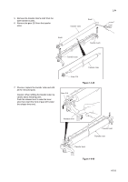
2JN 5. Remove the connector. 6. Remove the screw and then remove the inverter PWB. 7. Check or replace the inverter PWB and refit all the removed parts. Caution: Replace F1 with a fuse rated 250 V ac, 0.75 A, non-time delay, (when F1 fuse is replaced.) F1 CN1 Inverter PWB CN2 Inverter PWB Connector Screw 8. Unhook three hooks and then remove the ISU reflector. Figure 1-5-41 ISU reflector 9. Remove the exposure lamp from the holders. 10. Check or replace the exposure lamp and refit all the removed parts. Hook Hook Hook Figure 1-5-42 Exposure lamp Holder 1-5-28 Holder Lamp mount Figure 1-5-43
-
 1
1 -
2
-
3
-
4
-
5
-
6
-
7
-
8
-
9
-
10
-
11
-
12
-
13
-
14
-
15
-
16
-
17
-
18
-
19
-
20
-
21
-
22
-
23
-
24
-
25
-
26
-
27
-
28
-
29
-
30
-
31
-
32
-
33
-
34
-
35
-
36
-
37
-
38
-
39
-
40
-
41
-
42
-
43
-
44
-
45
-
46
-
47
-
48
-
49
-
50
-
51
-
52
-
53
-
54
-
55
-
56
-
57
-
58
-
59
-
60
-
61
-
62
-
63
-
64
-
65
-
66
-
67
-
68
-
69
-
70
-
71
-
72
-
73
-
74
-
75
-
76
-
77
-
78
-
79
-
80
-
81
-
82
-
83
-
84
-
85
-
86
-
87
-
88
-
89
-
90
-
91
-
92
-
93
-
94
-
95
-
96
-
97
-
98
-
99
-
100
-
101
-
102
-
103
-
104
-
105
-
106
-
107
-
108
-
109
-
110
-
111
-
112
-
113
-
114
-
115
-
116
-
117
-
118
-
119
-
120
-
121
-
122
-
123
-
124
-
125
-
126
-
127
-
128
-
129
-
130
-
131
-
132
-
133
-
134
-
135
-
136
-
137
-
138
-
139
-
140
-
141
-
142
-
143
-
144
-
145
-
146
-
147
-
148
-
149
-
150
-
151
-
152
-
153
-
154
-
155
-
156
-
157
-
158
-
159
-
160
-
161
-
162
-
163
-
164
-
165
-
166
-
167
-
168
-
169
-
170
-
171
-
172
-
173
-
174
-
 175
175 -
 176
176 -
 177
177 -
 178
178 -
 179
179 -
 180
180 -
 181
181 -
 182
182 -
 183
183 -
 184
184 -
 185
185 -
186
-
187
-
188
-
189
-
190
-
191
-
192
-
193
-
194
-
195
-
196
-
197
-
198
-
199
-
200
-
201
-
202
-
203
-
204
-
205
-
206
-
207
-
208
-
209
-
210
-
211
-
212
-
213
-
214
-
215
-
216
-
217
-
218
-
219
-
220
-
221
-
222
-
223
-
224
-
225
-
226
-
227
-
228
-
229
-
230
-
231
-
232
-
233
-
234
-
235
-
236
-
237
-
238
-
239
-
240
-
241
-
242
-
243
-
244
-
245
-
246
-
247
-
248
-
249
-
250
-
251
-
252
 |
 |

2JN
1-5-28
5.
Remove the connector.
6.
Remove the screw and then remove the
inverter PWB.
7.
Check or replace the inverter PWB and refit
all the removed parts.
Caution: Replace F1 with a fuse rated 250 V
ac, 0.75 A, non-time delay, (when F1 fuse is
replaced.)
Figure 1-5-41
8.
Unhook three hooks and then remove the
ISU reflector.
Figure 1-5-42
9.
Remove the exposure lamp from the hold-
ers.
10. Check or replace the exposure lamp and
refit all the removed parts.
Figure 1-5-43
Inverter PWB
Inverter PWB
Screw
Connector
CN2
CN1
F1
ISU reflector
Hook
Hook
Hook
Holder
Holder
Exposure lamp
Lamp mount