Dell PowerEdge 2950 Hardware Owner's Manual (PDF) - Page 103
SAS Backplane Board, Removing the SAS Backplane Board
 |
View all Dell PowerEdge 2950 manuals
Add to My Manuals
Save this manual to your list of manuals |
Page 103 highlights
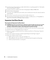
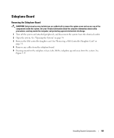
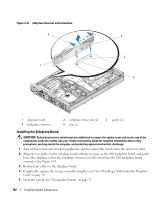
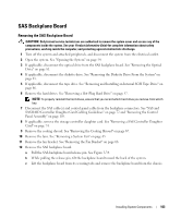
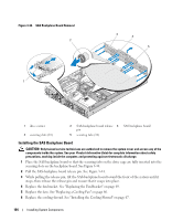
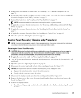
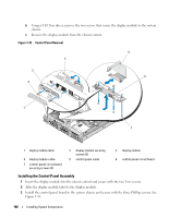
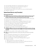
SAS Backplane Board Removing the SAS Backplane Board CAUTION: Only trained service technicians are authorized to remove the system cover and access any of the components inside the system. See your Product Information Guide for complete information about safety precautions, working inside the computer, and protecting against electrostatic discharge. 1 Turn off the system and attached peripherals, and disconnect the system from the electrical outlet. 2 Open the system. See "Opening the System" on page 54. 3 If applicable, disconnect the optical drive from the SAS backplane board. See "Removing the Optical Drive" on page 81. 4 If applicable, disconnect the diskette drive. See "Removing the Diskette Drive From the System" on page 83. 5 If applicable, disconnect the tape drive. See "Removing and Installing an Internal SCSI Tape Drive" on page 86. 6 Remove the hard drives. See "Removing a Hot-Plug Hard Drive" on page 57. NOTE: To properly reinstall the hard drives, ensure that you record which hard drive you remove from which bay. 7 Disconnect the SAS cable(s) and control panel cable from the backplane connectors. See "SAS and SAS RAID Controller Daughter Card Cabling Guidelines" on page 72 and "Removing the Control Panel Assembly" on page 105. 8 If applicable, remove the storage controller daughter card. See "Removing a SAS Controller Daughter Card" on page 74. 9 Remove the cooling shroud. See "Removing the Cooling Shroud" on page 67. 10 Remove the fans. See "Removing a System Fan" on page 65 11 Remove the fan bracket. See "Removing the Fan Bracket" on page 68. 12 Remove the SAS backplane board: a Pull the SAS-backplane board release pin. See Figure 3-34. b While pulling the release pin, tilt the backplane board toward the back of the system. c Lift the backplane board from its securing tabs and remove the backplane board from the chassis. Installing System Components 103
-
 1
1 -
2
-
3
-
4
-
5
-
6
-
7
-
8
-
9
-
10
-
11
-
12
-
13
-
14
-
15
-
16
-
17
-
18
-
19
-
20
-
21
-
22
-
23
-
24
-
25
-
26
-
27
-
28
-
29
-
30
-
31
-
32
-
33
-
34
-
35
-
36
-
37
-
38
-
39
-
40
-
41
-
42
-
43
-
44
-
45
-
46
-
47
-
48
-
49
-
50
-
51
-
52
-
53
-
54
-
55
-
56
-
57
-
58
-
59
-
60
-
61
-
62
-
63
-
64
-
65
-
66
-
67
-
68
-
69
-
70
-
71
-
72
-
73
-
74
-
75
-
76
-
77
-
78
-
79
-
80
-
81
-
82
-
83
-
84
-
85
-
86
-
87
-
88
-
89
-
90
-
91
-
92
-
93
-
94
-
95
-
96
-
97
-
 98
98 -
 99
99 -
 100
100 -
 101
101 -
 102
102 -
 103
103 -
 104
104 -
 105
105 -
 106
106 -
 107
107 -
 108
108 -
109
-
110
-
111
-
112
-
113
-
114
-
115
-
116
-
117
-
118
-
119
-
120
-
121
-
122
-
123
-
124
-
125
-
126
-
127
-
128
-
129
-
130
-
131
-
132
-
133
-
134
-
135
-
136
-
137
-
138
-
139
-
140
-
141
-
142
-
143
-
144
-
145
-
146
-
147
-
148
-
149
-
150
-
151
-
152
-
153
-
154
-
155
-
156
-
157
-
158
-
159
-
160
-
161
-
162
-
163
-
164
-
165
-
166
-
167
-
168
-
169
-
170
-
171
-
172
-
173
-
174
-
175
-
176
-
177
-
178
-
179
-
180
-
181
-
182
 |
 |