Dell PowerEdge 2950 Hardware Owner's Manual (PDF) - Page 14
Table 1-2., Front-Panel LED Indicators, Buttons, and Connectors, Indicator, Description - error codes
 |
View all Dell PowerEdge 2950 manuals
Add to My Manuals
Save this manual to your list of manuals |
Page 14 highlights
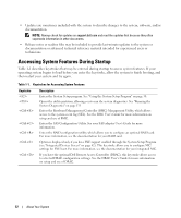
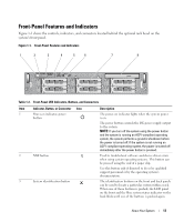
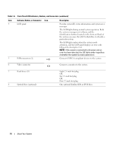
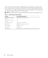
Table 1-2. Front-Panel LED Indicators, Buttons, and Connectors (continued) Item Indicator, Button, or Connector Icon 4 LCD panel 5 USB connectors (2) Description Provides system ID, status information, and system error messages. The LCD lights during normal system operation. Both the systems management software and the identification buttons located on the front and back of the system can cause the LCD to flash blue to identify a particular system. The LCD lights amber when the system needs attention, and the LCD panel displays an error code followed by descriptive text. NOTE: If the system is connected to AC power and an error has been detected, the LCD lights amber regardless of whether the system has been powered on. Connects USB 2.0-compliant devices to the system. 6 Video connector Connects a monitor to the system. 7 Hard drives (8) 8 Optical drive (optional) Eight 2.5-inch hot plug OR Six 3.5-inch hot plug OR Four 3.5-inch hot-plug One optional slimline IDE or DVD drive. 14 About Your System
-
 1
1 -
2
-
3
-
4
-
5
-
6
-
7
-
8
-
 9
9 -
 10
10 -
 11
11 -
 12
12 -
 13
13 -
 14
14 -
 15
15 -
 16
16 -
 17
17 -
 18
18 -
 19
19 -
20
-
21
-
22
-
23
-
24
-
25
-
26
-
27
-
28
-
29
-
30
-
31
-
32
-
33
-
34
-
35
-
36
-
37
-
38
-
39
-
40
-
41
-
42
-
43
-
44
-
45
-
46
-
47
-
48
-
49
-
50
-
51
-
52
-
53
-
54
-
55
-
56
-
57
-
58
-
59
-
60
-
61
-
62
-
63
-
64
-
65
-
66
-
67
-
68
-
69
-
70
-
71
-
72
-
73
-
74
-
75
-
76
-
77
-
78
-
79
-
80
-
81
-
82
-
83
-
84
-
85
-
86
-
87
-
88
-
89
-
90
-
91
-
92
-
93
-
94
-
95
-
96
-
97
-
98
-
99
-
100
-
101
-
102
-
103
-
104
-
105
-
106
-
107
-
108
-
109
-
110
-
111
-
112
-
113
-
114
-
115
-
116
-
117
-
118
-
119
-
120
-
121
-
122
-
123
-
124
-
125
-
126
-
127
-
128
-
129
-
130
-
131
-
132
-
133
-
134
-
135
-
136
-
137
-
138
-
139
-
140
-
141
-
142
-
143
-
144
-
145
-
146
-
147
-
148
-
149
-
150
-
151
-
152
-
153
-
154
-
155
-
156
-
157
-
158
-
159
-
160
-
161
-
162
-
163
-
164
-
165
-
166
-
167
-
168
-
169
-
170
-
171
-
172
-
173
-
174
-
175
-
176
-
177
-
178
-
179
-
180
-
181
-
182
 |
 |