Dell PowerEdge 2950 Hardware Owner's Manual (PDF) - Page 88
bracket from the chassis wall. See To replace the bracket
 |
View all Dell PowerEdge 2950 manuals
Add to My Manuals
Save this manual to your list of manuals |
Page 88 highlights
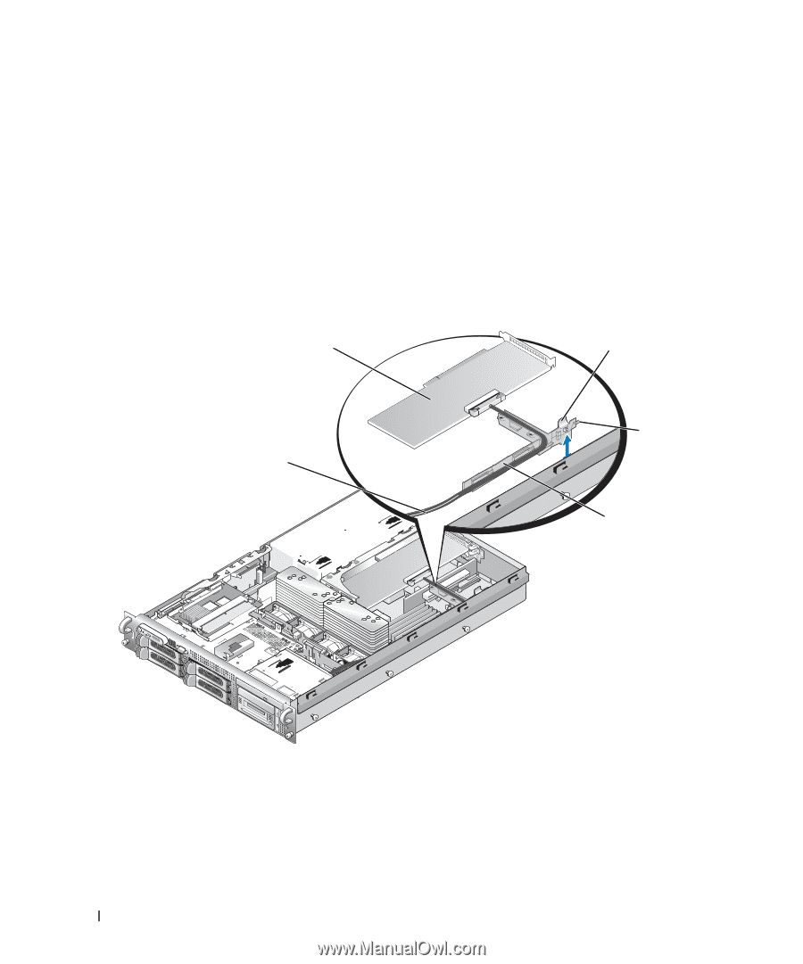
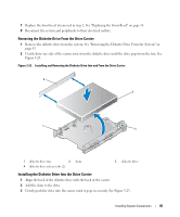
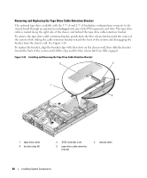
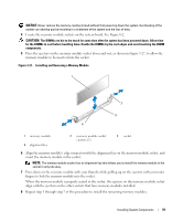
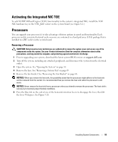
Removing and Replacing the Tape Drive Cable Retention Bracket The optional tape drive available with the 3.5" x4 and 2.5" x8 backplane configurations connects to the system board through an expansion card plugged into one of the PCI expansion card slots. The tape drive cable is routed along the right side of the chassis and behind the tape drive cable retention bracket. To remove the tape drive cable retention bracket, gently draw the blue release latch toward the center of the system while sliding the cable retention bracket toward the front of the system and disengaging the bracket from the chassis wall. See Figure 3-26. To replace the bracket, align the bracket clips with their slots on the chassis wall, then slide the bracket toward the back of the system until all the clips and the blue release latch are fully engaged. Figure 3-26. Installing and Removing the Tape Drive Cable Retention Bracket 2 3 4 1 5 1 tape drive cable 4 bracket clips (6) 2 SCSI controller card 5 tape drive cable retention bracket 3 release latch 88 Installing System Components
-
 1
1 -
2
-
3
-
4
-
5
-
6
-
7
-
8
-
9
-
10
-
11
-
12
-
13
-
14
-
15
-
16
-
17
-
18
-
19
-
20
-
21
-
22
-
23
-
24
-
25
-
26
-
27
-
28
-
29
-
30
-
31
-
32
-
33
-
34
-
35
-
36
-
37
-
38
-
39
-
40
-
41
-
42
-
43
-
44
-
45
-
46
-
47
-
48
-
49
-
50
-
51
-
52
-
53
-
54
-
55
-
56
-
57
-
58
-
59
-
60
-
61
-
62
-
63
-
64
-
65
-
66
-
67
-
68
-
69
-
70
-
71
-
72
-
73
-
74
-
75
-
76
-
77
-
78
-
79
-
80
-
81
-
82
-
 83
83 -
 84
84 -
 85
85 -
 86
86 -
 87
87 -
 88
88 -
 89
89 -
 90
90 -
 91
91 -
 92
92 -
 93
93 -
94
-
95
-
96
-
97
-
98
-
99
-
100
-
101
-
102
-
103
-
104
-
105
-
106
-
107
-
108
-
109
-
110
-
111
-
112
-
113
-
114
-
115
-
116
-
117
-
118
-
119
-
120
-
121
-
122
-
123
-
124
-
125
-
126
-
127
-
128
-
129
-
130
-
131
-
132
-
133
-
134
-
135
-
136
-
137
-
138
-
139
-
140
-
141
-
142
-
143
-
144
-
145
-
146
-
147
-
148
-
149
-
150
-
151
-
152
-
153
-
154
-
155
-
156
-
157
-
158
-
159
-
160
-
161
-
162
-
163
-
164
-
165
-
166
-
167
-
168
-
169
-
170
-
171
-
172
-
173
-
174
-
175
-
176
-
177
-
178
-
179
-
180
-
181
-
182
 |
 |