Dell PowerEdge 2950 Hardware Owner's Manual (PDF) - Page 17
Back-Panel Features and Indicators, Connecting External Devices - pci slots
 |
View all Dell PowerEdge 2950 manuals
Add to My Manuals
Save this manual to your list of manuals |
Page 17 highlights
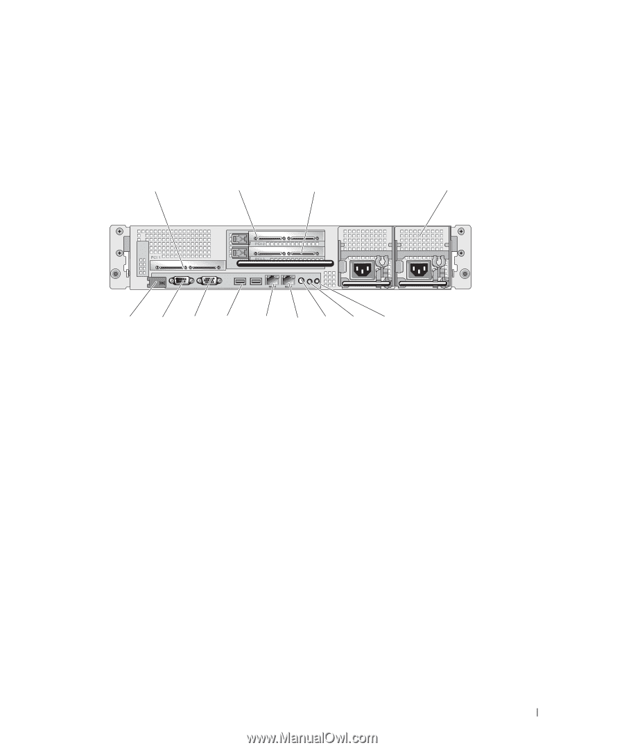
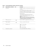
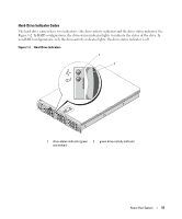
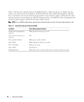
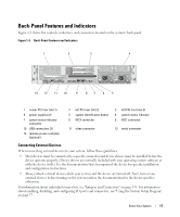
Back-Panel Features and Indicators Figure 1-3 shows the controls, indicators, and connectors located on the system's back panel. Figure 1-3. Back-Panel Features and Indicators 1 2 3 4 13 12 11 10 9 87 6 5 1 center PCI riser (slot 1) 4 power supplies (2) 7 system status indicator connector 10 USB connectors (2) 13 remote access controller (optional) 2 left PCI riser (slot 2) 5 system identification button 8 NIC2 connector 3 left PCI riser (slot 3) 6 system status indicator 9 NIC1 connector 11 video connector 12 serial connector Connecting External Devices When connecting external devices to your system, follow these guidelines: • Most devices must be connected to a specific connector and device drivers must be installed before the device operates properly. (Device drivers are normally included with your operating system software or with the device itself.) See the documentation that accompanied the device for specific installation and configuration instructions. • Always attach external devices while your system and the device are turned off. Next, turn on any external devices before turning on the system (unless the documentation for the device specifies otherwise). For information about individual connectors, see "Jumpers and Connectors" on page 135. For information about enabling, disabling, and configuring I/O ports and connectors, see "Using the System Setup Program" on page 37. About Your System 17
-
 1
1 -
2
-
3
-
4
-
5
-
6
-
7
-
8
-
9
-
10
-
11
-
 12
12 -
 13
13 -
 14
14 -
 15
15 -
 16
16 -
 17
17 -
 18
18 -
 19
19 -
 20
20 -
 21
21 -
 22
22 -
23
-
24
-
25
-
26
-
27
-
28
-
29
-
30
-
31
-
32
-
33
-
34
-
35
-
36
-
37
-
38
-
39
-
40
-
41
-
42
-
43
-
44
-
45
-
46
-
47
-
48
-
49
-
50
-
51
-
52
-
53
-
54
-
55
-
56
-
57
-
58
-
59
-
60
-
61
-
62
-
63
-
64
-
65
-
66
-
67
-
68
-
69
-
70
-
71
-
72
-
73
-
74
-
75
-
76
-
77
-
78
-
79
-
80
-
81
-
82
-
83
-
84
-
85
-
86
-
87
-
88
-
89
-
90
-
91
-
92
-
93
-
94
-
95
-
96
-
97
-
98
-
99
-
100
-
101
-
102
-
103
-
104
-
105
-
106
-
107
-
108
-
109
-
110
-
111
-
112
-
113
-
114
-
115
-
116
-
117
-
118
-
119
-
120
-
121
-
122
-
123
-
124
-
125
-
126
-
127
-
128
-
129
-
130
-
131
-
132
-
133
-
134
-
135
-
136
-
137
-
138
-
139
-
140
-
141
-
142
-
143
-
144
-
145
-
146
-
147
-
148
-
149
-
150
-
151
-
152
-
153
-
154
-
155
-
156
-
157
-
158
-
159
-
160
-
161
-
162
-
163
-
164
-
165
-
166
-
167
-
168
-
169
-
170
-
171
-
172
-
173
-
174
-
175
-
176
-
177
-
178
-
179
-
180
-
181
-
182
 |
 |