Dell PowerEdge 2950 Hardware Owner's Manual (PDF) - Page 91
Notice, Caution
 |
View all Dell PowerEdge 2950 manuals
Add to My Manuals
Save this manual to your list of manuals |
Page 91 highlights
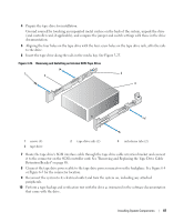
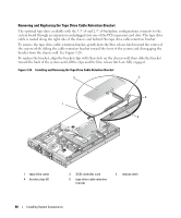
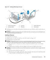
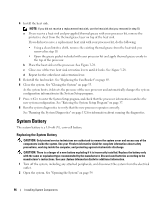
NOTICE: Never remove the memory cooling shroud without first powering down the system. Overheating of the system can develop quickly resulting in a shutdown of the system and the loss of data. 4 Locate the memory module sockets on the system board. See Figure 6-2. CAUTION: The DIMMs are hot to the touch for some time after the system has been powered down. Allow time for the DIMMs to cool before handling them. Handle the DIMMs by the card edges and avoid touching the DIMM components. 5 Press the ejectors on the memory module socket down and out, as shown in Figure 3-27, to allow the memory module to be inserted into the socket. Figure 3-27. Installing and Removing a Memory Module 1 2 3 4 1 memory module 4 alignment key 2 memory module socket ejectors (2) 3 socket 6 Align the memory module's edge connector with the alignment key on the memory module socket, and insert the memory module in the socket. NOTE: The memory module socket has an alignment key that allows you to install the memory module in the socket in only one way. 7 Press down on the memory module with your thumbs while pulling up on the ejectors with your index fingers to lock the memory module into the socket. When the memory module is properly seated in the socket, the ejectors on the memory module socket align with the ejectors on the other sockets that have memory modules installed. 8 Repeat step 3 through step 7 of this procedure to install the remaining memory modules. Installing System Components 91
-
 1
1 -
2
-
3
-
4
-
5
-
6
-
7
-
8
-
9
-
10
-
11
-
12
-
13
-
14
-
15
-
16
-
17
-
18
-
19
-
20
-
21
-
22
-
23
-
24
-
25
-
26
-
27
-
28
-
29
-
30
-
31
-
32
-
33
-
34
-
35
-
36
-
37
-
38
-
39
-
40
-
41
-
42
-
43
-
44
-
45
-
46
-
47
-
48
-
49
-
50
-
51
-
52
-
53
-
54
-
55
-
56
-
57
-
58
-
59
-
60
-
61
-
62
-
63
-
64
-
65
-
66
-
67
-
68
-
69
-
70
-
71
-
72
-
73
-
74
-
75
-
76
-
77
-
78
-
79
-
80
-
81
-
82
-
83
-
84
-
85
-
 86
86 -
 87
87 -
 88
88 -
 89
89 -
 90
90 -
 91
91 -
 92
92 -
 93
93 -
 94
94 -
 95
95 -
 96
96 -
97
-
98
-
99
-
100
-
101
-
102
-
103
-
104
-
105
-
106
-
107
-
108
-
109
-
110
-
111
-
112
-
113
-
114
-
115
-
116
-
117
-
118
-
119
-
120
-
121
-
122
-
123
-
124
-
125
-
126
-
127
-
128
-
129
-
130
-
131
-
132
-
133
-
134
-
135
-
136
-
137
-
138
-
139
-
140
-
141
-
142
-
143
-
144
-
145
-
146
-
147
-
148
-
149
-
150
-
151
-
152
-
153
-
154
-
155
-
156
-
157
-
158
-
159
-
160
-
161
-
162
-
163
-
164
-
165
-
166
-
167
-
168
-
169
-
170
-
171
-
172
-
173
-
174
-
175
-
176
-
177
-
178
-
179
-
180
-
181
-
182
 |
 |