Dell PowerEdge 2950 Hardware Owner's Manual (PDF) - Page 95
Installing a Processor, nstall the processor in the socket.
 |
View all Dell PowerEdge 2950 manuals
Add to My Manuals
Save this manual to your list of manuals |
Page 95 highlights
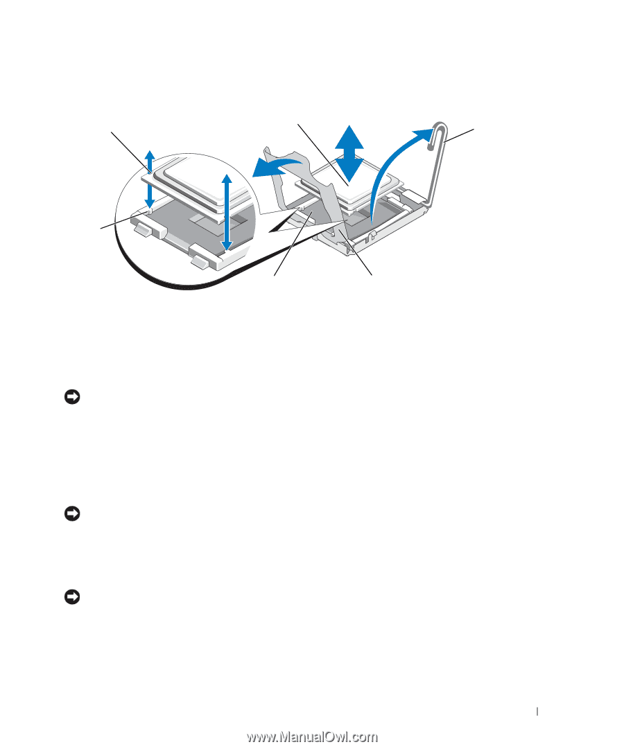
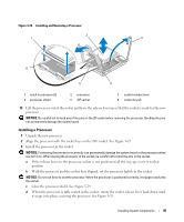
Figure 3-29. Installing and Removing a Processor 2 1 3 6 5 4 1 notch in processor (2) 4 processor shield 2 processor 5 ZIF socket 3 socket-release lever 6 socket key (2) 13 Lift the processor out of the socket and leave the release lever up so that the socket is ready for the new processor. NOTICE: Be careful not to bend any of the pins on the ZIF socket when removing the processor. Bending the pins can permanently damage the system board. Installing a Processor 1 Unpack the new processor. 2 Align the processor with the socket keys on the ZIF socket. See Figure 3-29. 3 Install the processor in the socket. NOTICE: Positioning the processor incorrectly can permanently damage the system board or the processor when you turn it on. When placing the processor in the socket, be careful not to bend the pins in the socket. a If the release lever on the processor socket is not positioned all the way up, move it to that position. b With the processor and the socket keys aligned, set the processor lightly in the socket. NOTICE: Do not use force to seat the processor. When the processor is positioned correctly, it engages easily into the socket. c Close the processor shield. See Figure 3-29. d When the processor is fully seated in the socket, rotate the socket release lever back down until it snaps into place, securing the processor. See Figure 3-29. Installing System Components 95
-
 1
1 -
2
-
3
-
4
-
5
-
6
-
7
-
8
-
9
-
10
-
11
-
12
-
13
-
14
-
15
-
16
-
17
-
18
-
19
-
20
-
21
-
22
-
23
-
24
-
25
-
26
-
27
-
28
-
29
-
30
-
31
-
32
-
33
-
34
-
35
-
36
-
37
-
38
-
39
-
40
-
41
-
42
-
43
-
44
-
45
-
46
-
47
-
48
-
49
-
50
-
51
-
52
-
53
-
54
-
55
-
56
-
57
-
58
-
59
-
60
-
61
-
62
-
63
-
64
-
65
-
66
-
67
-
68
-
69
-
70
-
71
-
72
-
73
-
74
-
75
-
76
-
77
-
78
-
79
-
80
-
81
-
82
-
83
-
84
-
85
-
86
-
87
-
88
-
89
-
 90
90 -
 91
91 -
 92
92 -
 93
93 -
 94
94 -
 95
95 -
 96
96 -
 97
97 -
 98
98 -
 99
99 -
 100
100 -
101
-
102
-
103
-
104
-
105
-
106
-
107
-
108
-
109
-
110
-
111
-
112
-
113
-
114
-
115
-
116
-
117
-
118
-
119
-
120
-
121
-
122
-
123
-
124
-
125
-
126
-
127
-
128
-
129
-
130
-
131
-
132
-
133
-
134
-
135
-
136
-
137
-
138
-
139
-
140
-
141
-
142
-
143
-
144
-
145
-
146
-
147
-
148
-
149
-
150
-
151
-
152
-
153
-
154
-
155
-
156
-
157
-
158
-
159
-
160
-
161
-
162
-
163
-
164
-
165
-
166
-
167
-
168
-
169
-
170
-
171
-
172
-
173
-
174
-
175
-
176
-
177
-
178
-
179
-
180
-
181
-
182
 |
 |