Dell PowerEdge 2950 Hardware Owner's Manual (PDF) - Page 55
Closing the System, Hard Drives - sas backplane
 |
View all Dell PowerEdge 2950 manuals
Add to My Manuals
Save this manual to your list of manuals |
Page 55 highlights
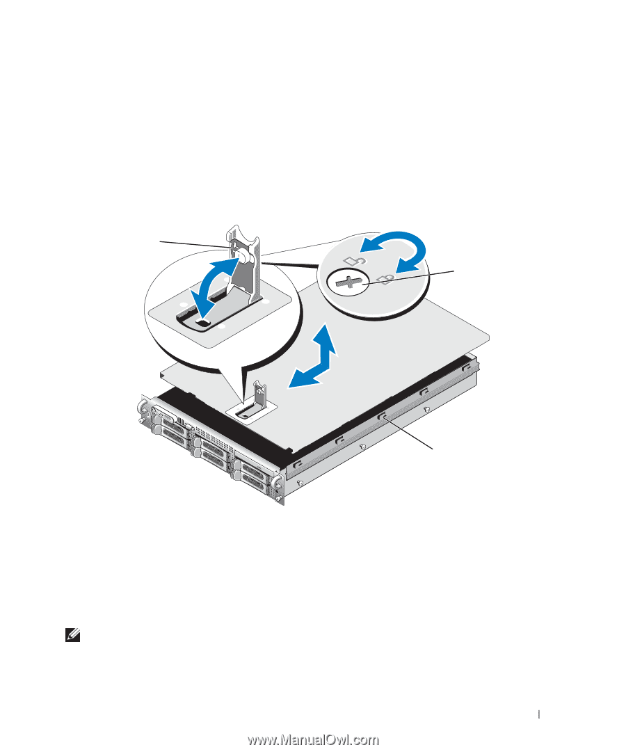
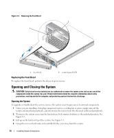
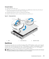
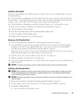
Closing the System 1 Lift up the latch on the cover. 2 Place the cover on top of the system and offset the cover slightly back so that it clears the chassis J hooks and lays flush on the system chassis. See Figure 3-3. 3 Push down the latch to lever the cover into the closed position. 4 Rotate the latch release lock in a clockwise direction to secure the cover. Figure 3-3. Removing the Cover 1 2 3 1 latch 2 latch release lock 3 alignment J hooks Hard Drives This subsection describes how to install and configure SAS or SATA hard drives in the system's internal hard-drive bays. Your system features up to six 3.5-inch hard drives, or eight 2.5-inch hard drives. All drives connect to the system board through one of three optional SAS backplane boards. See "SAS Backplane Board Connectors" on page 139 for information on these backplane options. NOTE: Depending on the hard drive configuration you ordered, your hard drive(s) may come with a drive interposer that allows your SATA drive to attach to the SAS connector on the backplane. Installing System Components 55
-
 1
1 -
2
-
3
-
4
-
5
-
6
-
7
-
8
-
9
-
10
-
11
-
12
-
13
-
14
-
15
-
16
-
17
-
18
-
19
-
20
-
21
-
22
-
23
-
24
-
25
-
26
-
27
-
28
-
29
-
30
-
31
-
32
-
33
-
34
-
35
-
36
-
37
-
38
-
39
-
40
-
41
-
42
-
43
-
44
-
45
-
46
-
47
-
48
-
49
-
 50
50 -
 51
51 -
 52
52 -
 53
53 -
 54
54 -
 55
55 -
 56
56 -
 57
57 -
 58
58 -
 59
59 -
 60
60 -
61
-
62
-
63
-
64
-
65
-
66
-
67
-
68
-
69
-
70
-
71
-
72
-
73
-
74
-
75
-
76
-
77
-
78
-
79
-
80
-
81
-
82
-
83
-
84
-
85
-
86
-
87
-
88
-
89
-
90
-
91
-
92
-
93
-
94
-
95
-
96
-
97
-
98
-
99
-
100
-
101
-
102
-
103
-
104
-
105
-
106
-
107
-
108
-
109
-
110
-
111
-
112
-
113
-
114
-
115
-
116
-
117
-
118
-
119
-
120
-
121
-
122
-
123
-
124
-
125
-
126
-
127
-
128
-
129
-
130
-
131
-
132
-
133
-
134
-
135
-
136
-
137
-
138
-
139
-
140
-
141
-
142
-
143
-
144
-
145
-
146
-
147
-
148
-
149
-
150
-
151
-
152
-
153
-
154
-
155
-
156
-
157
-
158
-
159
-
160
-
161
-
162
-
163
-
164
-
165
-
166
-
167
-
168
-
169
-
170
-
171
-
172
-
173
-
174
-
175
-
176
-
177
-
178
-
179
-
180
-
181
-
182
 |
 |