Dell PowerEdge 2950 Hardware Owner's Manual (PDF) - Page 81
Optical Drive, Removing the Optical Drive - bezel
 |
View all Dell PowerEdge 2950 manuals
Add to My Manuals
Save this manual to your list of manuals |
Page 81 highlights
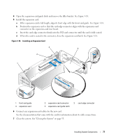
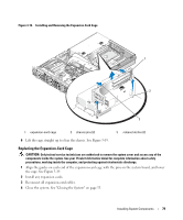
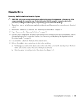
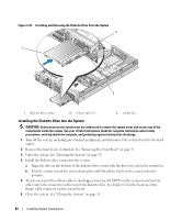
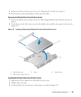
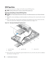
6 Align the front edge of the RAC card with the two front plastic retention standoffs adjacent to the RAC system board connector, and press down the side of the card until it is fully seated. See Figure 3-20. When the front of the card is fully seated, the plastic standoff snaps over the edge of the card. 7 Connect the two short ribbon cables to the RAC card and the system board. See Figure 6-2 for the connector locations NOTICE: Be careful when attaching cables to the system board that you do not damage the surrounding system board components. a Connect one cable to connector 1 on the RAC card and to RAC_CONN1 on the system board. b Connect the second cable to connector 2 on the RAC card and to RAC_CONN2 on the system board. Reinstall the central riser board. See "Installing the Central Riser Board" on page 100. NOTICE: When detaching the RAC cables from the system board, squeeze the metal ends of the cable connectors and gently work the connector out of the socket. Do not pull on the cable to unseat the connector. Doing so can damage the cable. 8 Close the system. See "Closing the System" on page 55. 9 Reconnect the system and peripherals to their power sources, and turn them on. See the RAC card documentation for information on configuring and using the RAC card. Optical Drive An optional slimline optical drive is mounted on a tray that slides in the front panel and connects to the controllers on the system board through the SAS backplane board. Removing the Optical Drive CAUTION: Only trained service technicians are authorized to remove the system cover and access any of the components inside the system. See your Product Information Guide for complete information about safety precautions, working inside the computer, and protecting against electrostatic discharge. 1 Turn off the system, including any attached peripherals, and disconnect the system from its electrical outlet. 2 Remove the bezel. See "Removing the Front Bezel" on page 53. 3 Open the system. See "Opening the System" on page 54 4 Disconnect the optical drive cable from the back of the drive. 5 To remove the optical drive, press down and forward on the blue tray release tab and slide the drive tray out of the system. See Figure 3-21. Installing System Components 81
-
 1
1 -
2
-
3
-
4
-
5
-
6
-
7
-
8
-
9
-
10
-
11
-
12
-
13
-
14
-
15
-
16
-
17
-
18
-
19
-
20
-
21
-
22
-
23
-
24
-
25
-
26
-
27
-
28
-
29
-
30
-
31
-
32
-
33
-
34
-
35
-
36
-
37
-
38
-
39
-
40
-
41
-
42
-
43
-
44
-
45
-
46
-
47
-
48
-
49
-
50
-
51
-
52
-
53
-
54
-
55
-
56
-
57
-
58
-
59
-
60
-
61
-
62
-
63
-
64
-
65
-
66
-
67
-
68
-
69
-
70
-
71
-
72
-
73
-
74
-
75
-
 76
76 -
 77
77 -
 78
78 -
 79
79 -
 80
80 -
 81
81 -
 82
82 -
 83
83 -
 84
84 -
 85
85 -
 86
86 -
87
-
88
-
89
-
90
-
91
-
92
-
93
-
94
-
95
-
96
-
97
-
98
-
99
-
100
-
101
-
102
-
103
-
104
-
105
-
106
-
107
-
108
-
109
-
110
-
111
-
112
-
113
-
114
-
115
-
116
-
117
-
118
-
119
-
120
-
121
-
122
-
123
-
124
-
125
-
126
-
127
-
128
-
129
-
130
-
131
-
132
-
133
-
134
-
135
-
136
-
137
-
138
-
139
-
140
-
141
-
142
-
143
-
144
-
145
-
146
-
147
-
148
-
149
-
150
-
151
-
152
-
153
-
154
-
155
-
156
-
157
-
158
-
159
-
160
-
161
-
162
-
163
-
164
-
165
-
166
-
167
-
168
-
169
-
170
-
171
-
172
-
173
-
174
-
175
-
176
-
177
-
178
-
179
-
180
-
181
-
182
 |
 |
