Dell PowerEdge 2950 Hardware Owner's Manual (PDF) - Page 87
Connect the tape drive power cable to the tape drive power connector on the backplane. See - software
 |
View all Dell PowerEdge 2950 manuals
Add to My Manuals
Save this manual to your list of manuals |
Page 87 highlights
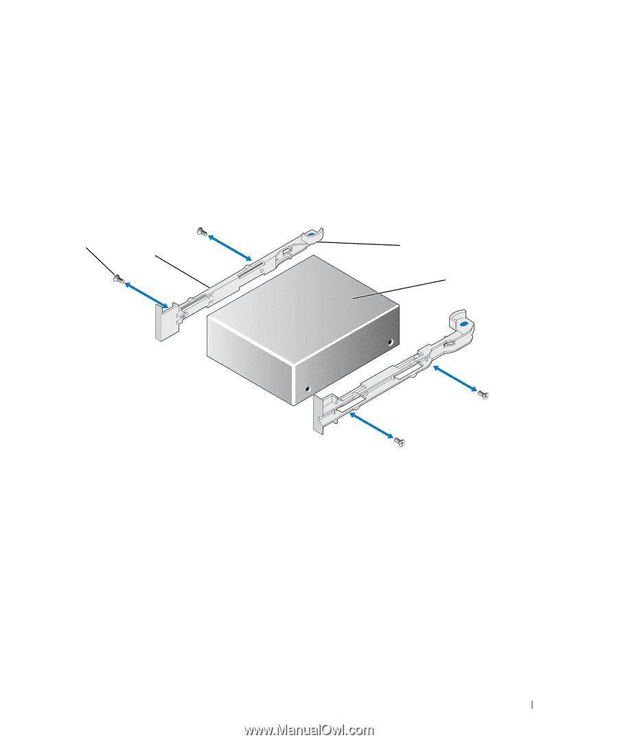
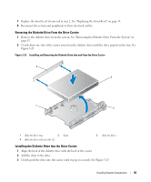
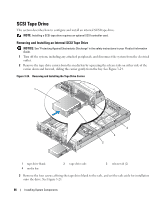
4 Prepare the tape drive for installation. Ground yourself by touching an unpainted metal surface on the back of the system, unpack the drive (and controller card, if applicable), and compare the jumper and switch settings with those in the drive documentation. 5 Aligning the four holes on the tape drive with the four screw holes on the tape drive rails, affix the rails to the drive. 6 Insert the tape drive along the rails in the media bay. See Figure 3-25. Figure 3-25. Removing and Installing an Internal SCSI Tape Drive 1 2 3 4 1 screws (4) 4 tape drive 2 tape drive rails (2) 3 rail release tabs (2) 7 Route the tape drive's SCSI interface cable through the tape drive cable retention bracket and connect it to the connector on the SCSI controller card. See "Removing and Replacing the Tape Drive Cable Retention Bracket" on page 88. 8 Connect the tape drive power cable to the tape drive power connector on the backplane. See Figure 6-4 or Figure 6-5 for the connector location. 9 Reconnect the system to its electrical outlet and turn the system on, including any attached peripherals. 10 Perform a tape backup and verification test with the drive as instructed in the software documentation that came with the drive. Installing System Components 87
-
 1
1 -
2
-
3
-
4
-
5
-
6
-
7
-
8
-
9
-
10
-
11
-
12
-
13
-
14
-
15
-
16
-
17
-
18
-
19
-
20
-
21
-
22
-
23
-
24
-
25
-
26
-
27
-
28
-
29
-
30
-
31
-
32
-
33
-
34
-
35
-
36
-
37
-
38
-
39
-
40
-
41
-
42
-
43
-
44
-
45
-
46
-
47
-
48
-
49
-
50
-
51
-
52
-
53
-
54
-
55
-
56
-
57
-
58
-
59
-
60
-
61
-
62
-
63
-
64
-
65
-
66
-
67
-
68
-
69
-
70
-
71
-
72
-
73
-
74
-
75
-
76
-
77
-
78
-
79
-
80
-
81
-
 82
82 -
 83
83 -
 84
84 -
 85
85 -
 86
86 -
 87
87 -
 88
88 -
 89
89 -
 90
90 -
 91
91 -
 92
92 -
93
-
94
-
95
-
96
-
97
-
98
-
99
-
100
-
101
-
102
-
103
-
104
-
105
-
106
-
107
-
108
-
109
-
110
-
111
-
112
-
113
-
114
-
115
-
116
-
117
-
118
-
119
-
120
-
121
-
122
-
123
-
124
-
125
-
126
-
127
-
128
-
129
-
130
-
131
-
132
-
133
-
134
-
135
-
136
-
137
-
138
-
139
-
140
-
141
-
142
-
143
-
144
-
145
-
146
-
147
-
148
-
149
-
150
-
151
-
152
-
153
-
154
-
155
-
156
-
157
-
158
-
159
-
160
-
161
-
162
-
163
-
164
-
165
-
166
-
167
-
168
-
169
-
170
-
171
-
172
-
173
-
174
-
175
-
176
-
177
-
178
-
179
-
180
-
181
-
182
 |
 |