Dell PowerEdge 2950 Hardware Owner's Manual (PDF) - Page 90
Non-Optimal Memory Configurations, Memory Sparing Support, Installing Memory Modules
 |
View all Dell PowerEdge 2950 manuals
Add to My Manuals
Save this manual to your list of manuals |
Page 90 highlights
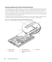
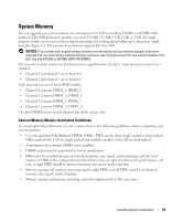
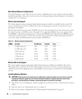
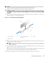
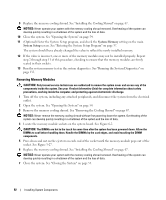
Non-Optimal Memory Configurations System performance can be affected if your memory configuration does not conform to the preceding installation guidelines. Your system may issue an error message during startup stating that your memory configuration is non-optimal. Memory Sparing Support The system supports memory sparing if eight identical memory modules are installed in the system. The memory sparing feature must be enabled in the System Setup program and can be used only if memory mirroring is not enabled. Memory sparing allocates four ranks of DIMM memory to the spare bank. These four ranks consist of the first rank of memory in DIMM sockets 1 through 4. For single-rank DIMMs, the entire capacity of the four DIMMs is allocated to sparing whereas for dual-rank DIMMs, only half of the four-DIMM capacity is allocated to sparing. Table 3-2 shows how memory sparing splits the available and spared memory in each of the single- and dual-ranked memory module combinations. Table 3-2. Memory Sparing Configurations DIMMs 8 Size/Type 256-MB single-rank 512-MB single-rank 1-GB single-rank 2-GB single-rank 2-GB dual-rank 4-GB dual-rank Total Memory 2 GB 4 GB 8 GB 16 GB 16 GB 32 GB Available 1 GB 2 GB 4 GB 8 GB 12 GB 24 GB Spare 1 GB 2 GB 4 GB 8 GB 4 GB 8 GB Memory Mirroring Support The system supports memory mirroring if eight identical memory modules are installed in the system. Mirroring must be enabled in the System Setup program and can be used only if memory sparing is not enabled. In a mirrored configuration, the total available system memory is one-half of the total installed memory. Installing Memory Modules CAUTION: Only trained service technicians are authorized to remove the system cover and access any of the components inside the system. See your Product Information Guide for complete information about safety precautions, working inside the computer, and protecting against electrostatic discharge. 1 Turn off the system, including any attached peripherals, and disconnect the system from the electrical outlet. 2 Open the system. See "Opening the System" on page 54. 3 Remove the memory cooling shroud. See "Removing the Cooling Shroud" on page 67. 90 Installing System Components
-
 1
1 -
2
-
3
-
4
-
5
-
6
-
7
-
8
-
9
-
10
-
11
-
12
-
13
-
14
-
15
-
16
-
17
-
18
-
19
-
20
-
21
-
22
-
23
-
24
-
25
-
26
-
27
-
28
-
29
-
30
-
31
-
32
-
33
-
34
-
35
-
36
-
37
-
38
-
39
-
40
-
41
-
42
-
43
-
44
-
45
-
46
-
47
-
48
-
49
-
50
-
51
-
52
-
53
-
54
-
55
-
56
-
57
-
58
-
59
-
60
-
61
-
62
-
63
-
64
-
65
-
66
-
67
-
68
-
69
-
70
-
71
-
72
-
73
-
74
-
75
-
76
-
77
-
78
-
79
-
80
-
81
-
82
-
83
-
84
-
 85
85 -
 86
86 -
 87
87 -
 88
88 -
 89
89 -
 90
90 -
 91
91 -
 92
92 -
 93
93 -
 94
94 -
 95
95 -
96
-
97
-
98
-
99
-
100
-
101
-
102
-
103
-
104
-
105
-
106
-
107
-
108
-
109
-
110
-
111
-
112
-
113
-
114
-
115
-
116
-
117
-
118
-
119
-
120
-
121
-
122
-
123
-
124
-
125
-
126
-
127
-
128
-
129
-
130
-
131
-
132
-
133
-
134
-
135
-
136
-
137
-
138
-
139
-
140
-
141
-
142
-
143
-
144
-
145
-
146
-
147
-
148
-
149
-
150
-
151
-
152
-
153
-
154
-
155
-
156
-
157
-
158
-
159
-
160
-
161
-
162
-
163
-
164
-
165
-
166
-
167
-
168
-
169
-
170
-
171
-
172
-
173
-
174
-
175
-
176
-
177
-
178
-
179
-
180
-
181
-
182
 |
 |