Dell bpcwcsn_5 User's Guide - Page 247
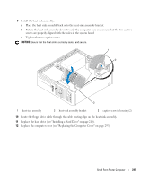
Route the floppy drive cable through the cable routing clips on the heat sink assembly.
 |
View all Dell bpcwcsn_5 manuals
Add to My Manuals
Save this manual to your list of manuals |
Page 247 highlights
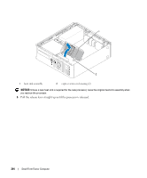
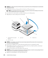
9 Install the heat sink assembly: a Place the heat sink assembly back onto the heat-sink assembly bracket. b Rotate the heat sink assembly down towards the computer base and ensure that the two captive screws are properly aligned with the holes in the system board c Tighten the two captive screws. NOTICE: Ensure that the heat sink is correctly seated and secure. 1 2 3 1 heat sink assembly 2 heat-sink assembly bracket 3 captive screw in housing (2) 10 Route the floppy drive cable through the cable routing clips on the heat sink assembly. 11 Replace the hard drive (see "Installing a Hard Drive" on page 210). 12 Replace the computer cover (see "Replacing the Computer Cover" on page 297). Small Form Factor Computer 247
-
 1
1 -
2
-
3
-
4
-
5
-
6
-
7
-
8
-
9
-
10
-
11
-
12
-
13
-
14
-
15
-
16
-
17
-
18
-
19
-
20
-
21
-
22
-
23
-
24
-
25
-
26
-
27
-
28
-
29
-
30
-
31
-
32
-
33
-
34
-
35
-
36
-
37
-
38
-
39
-
40
-
41
-
42
-
43
-
44
-
45
-
46
-
47
-
48
-
49
-
50
-
51
-
52
-
53
-
54
-
55
-
56
-
57
-
58
-
59
-
60
-
61
-
62
-
63
-
64
-
65
-
66
-
67
-
68
-
69
-
70
-
71
-
72
-
73
-
74
-
75
-
76
-
77
-
78
-
79
-
80
-
81
-
82
-
83
-
84
-
85
-
86
-
87
-
88
-
89
-
90
-
91
-
92
-
93
-
94
-
95
-
96
-
97
-
98
-
99
-
100
-
101
-
102
-
103
-
104
-
105
-
106
-
107
-
108
-
109
-
110
-
111
-
112
-
113
-
114
-
115
-
116
-
117
-
118
-
119
-
120
-
121
-
122
-
123
-
124
-
125
-
126
-
127
-
128
-
129
-
130
-
131
-
132
-
133
-
134
-
135
-
136
-
137
-
138
-
139
-
140
-
141
-
142
-
143
-
144
-
145
-
146
-
147
-
148
-
149
-
150
-
151
-
152
-
153
-
154
-
155
-
156
-
157
-
158
-
159
-
160
-
161
-
162
-
163
-
164
-
165
-
166
-
167
-
168
-
169
-
170
-
171
-
172
-
173
-
174
-
175
-
176
-
177
-
178
-
179
-
180
-
181
-
182
-
183
-
184
-
185
-
186
-
187
-
188
-
189
-
190
-
191
-
192
-
193
-
194
-
195
-
196
-
197
-
198
-
199
-
200
-
201
-
202
-
203
-
204
-
205
-
206
-
207
-
208
-
209
-
210
-
211
-
212
-
213
-
214
-
215
-
216
-
217
-
218
-
219
-
220
-
221
-
222
-
223
-
224
-
225
-
226
-
227
-
228
-
229
-
230
-
231
-
232
-
233
-
234
-
235
-
236
-
237
-
238
-
239
-
240
-
241
-
 242
242 -
 243
243 -
 244
244 -
 245
245 -
 246
246 -
 247
247 -
 248
248 -
 249
249 -
 250
250 -
 251
251 -
 252
252 -
253
-
254
-
255
-
256
-
257
-
258
-
259
-
260
-
261
-
262
-
263
-
264
-
265
-
266
-
267
-
268
-
269
-
270
-
271
-
272
-
273
-
274
-
275
-
276
-
277
-
278
-
279
-
280
-
281
-
282
-
283
-
284
-
285
-
286
-
287
-
288
-
289
-
290
-
291
-
292
-
293
-
294
-
295
-
296
-
297
-
298
-
299
-
300
-
301
-
302
-
303
-
304
-
305
-
306
-
307
-
308
-
309
-
310
-
311
-
312
-
313
-
314
-
315
-
316
-
317
-
318
-
319
-
320
-
321
-
322
-
323
-
324
-
325
-
326
-
327
-
328
-
329
-
330
-
331
-
332
-
333
-
334
-
335
-
336
-
337
-
338
-
339
-
340
-
341
-
342
-
343
-
344
-
345
-
346
-
347
-
348
-
349
-
350
-
351
-
352
-
353
-
354
-
355
-
356
-
357
-
358
-
359
-
360
-
361
-
362
-
363
-
364
-
365
-
366
-
367
-
368
 |
 |

Small Form Factor Computer
247
9
Install the heat sink assembly:
a
Place the heat sink assembly back onto the heat-sink assembly bracket.
b
Rotate the heat sink assembly down towards the computer base and ensure that the two captive
screws are properly aligned with the holes in the system board
c
Tighten the two captive screws.
NOTICE:
Ensure that the heat sink is correctly seated and secure.
10
Route the floppy drive cable through the cable routing clips on the heat sink assembly.
11
Replace the hard drive (see "Installing a Hard Drive" on page 210).
12
Replace the computer cover (see "Replacing the Computer Cover" on page 297).
1
heat sink assembly
2
heat-sink assembly bracket
3
captive screw in housing (2)
3
1
2