HP ElitePad 1000 HP ElitePad 1000 G2 Maintenance and Service Guide - Page 38
Removal and replacement procedures, Tablet component replacement procedures, Display assembly
 |
View all HP ElitePad 1000 manuals
Add to My Manuals
Save this manual to your list of manuals |
Page 38 highlights
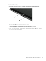
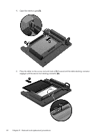
5 Removal and replacement procedures CAUTION: Components described in this chapter should only be accessed by an authorized service provider. Accessing these parts can damage the computer or void the warranty. NOTE: HP continually improves and changes product parts. For complete and current information on supported parts for your computer, go to http://partsurfer.hp.com, select your country or region, and then follow the on-screen instructions. Tablet component replacement procedures This chapter provides removal and replacement procedures for Authorized Service Provider only parts. There are as many as 34 screws that must be removed, replaced, and/or loosened when servicing the tablet. Make special note of each screw size and location during removal and replacement. Display assembly Description 10.1-in., WUXGA (1900×1200), UWVA, 50% CG, 400-nit, active pen and MultiTouch capacitive digitizer, chemically-strengthened glass with anti-smudge; includes display panel, display LVDS cable, TouchScreen cable, and display panel support rubber Spare part number 747658-001 Before disassembling the tablet, follow these steps: 1. Turn off the tablet. If you are unsure whether the tablet is off or in Hibernation, turn the tablet on, and then shut it down through the operating system. 2. Disconnect the power from the tablet by unplugging the power cord from the tablet. 3. Disconnect all external devices from the tablet. 30 Chapter 5 Removal and replacement procedures
-
 1
1 -
2
-
3
-
4
-
5
-
6
-
7
-
8
-
9
-
10
-
11
-
12
-
13
-
14
-
15
-
16
-
17
-
18
-
19
-
20
-
21
-
22
-
23
-
24
-
25
-
26
-
27
-
28
-
29
-
30
-
31
-
32
-
 33
33 -
 34
34 -
 35
35 -
 36
36 -
 37
37 -
 38
38 -
 39
39 -
 40
40 -
 41
41 -
 42
42 -
 43
43 -
44
-
45
-
46
-
47
-
48
-
49
-
50
-
51
-
52
-
53
-
54
-
55
-
56
-
57
-
58
-
59
-
60
-
61
-
62
-
63
-
64
-
65
-
66
-
67
-
68
-
69
-
70
-
71
-
72
-
73
-
74
-
75
-
76
-
77
-
78
-
79
-
80
-
81
-
82
-
83
-
84
-
85
-
86
-
87
-
88
-
89
-
90
-
91
-
92
-
93
-
94
-
95
-
96
-
97
-
98
-
99
-
100
-
101
-
102
-
103
-
104
-
105
-
106
-
107
-
108
-
109
-
110
-
111
-
112
-
113
-
114
-
115
-
116
-
117
-
118
-
119
-
120
 |
 |