HP ElitePad 1000 HP ElitePad 1000 G2 Maintenance and Service Guide - Page 66
Slot cover
 |
View all HP ElitePad 1000 manuals
Add to My Manuals
Save this manual to your list of manuals |
Page 66 highlights
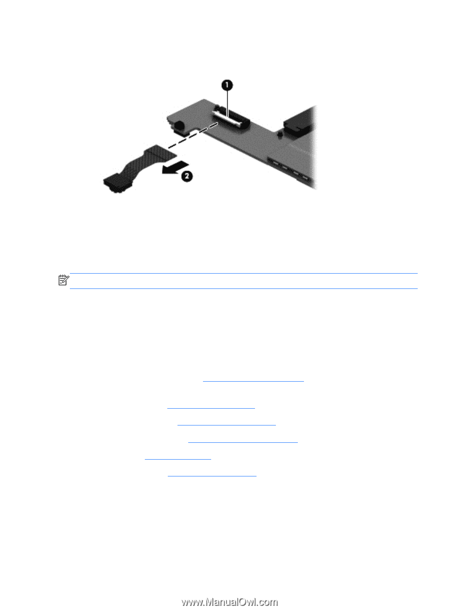
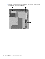
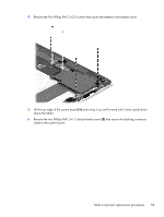
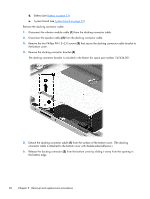
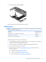
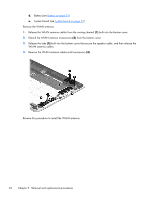
2. Release the ZIF connector (1) to which the forward-facing webcam cable is attached, and then disconnect the forward-facing webcam cable (2) from the system board. 3. Remove the forward-facing webcam and cable. Reverse this procedure to install the forward-facing webcam. Slot cover NOTE: The slot cover is included in the Button Kit, spare part number 747634-001. Before removing the slot cover, follow these steps: 1. Turn off the tablet. If you are unsure whether the tablet is off or in Hibernation, turn the tablet on, and then shut it down through the operating system. 2. Disconnect the power from the tablet by unplugging the power cord from the tablet. 3. Disconnect all external devices from the tablet. 4. Remove the display assembly (see Display assembly on page 30), and then remove the following components: a. NFC antenna (see NFC antenna on page 38) b. WWAN module (see WWAN module on page 39) c. Power button board (see Power button board on page 45) d. Battery (see Battery on page 51) e. System board (see System board on page 53) Remove the slot cover: 1. Remove the four Phillips PM1.3×2.0 screws (1) that secure the slot cover retention bracket and spring bracket to the bottom cover. 2. Remove the slot cover retention bracket (2) and the slot cover spring bracket (3). 58 Chapter 5 Removal and replacement procedures
-
 1
1 -
2
-
3
-
4
-
5
-
6
-
7
-
8
-
9
-
10
-
11
-
12
-
13
-
14
-
15
-
16
-
17
-
18
-
19
-
20
-
21
-
22
-
23
-
24
-
25
-
26
-
27
-
28
-
29
-
30
-
31
-
32
-
33
-
34
-
35
-
36
-
37
-
38
-
39
-
40
-
41
-
42
-
43
-
44
-
45
-
46
-
47
-
48
-
49
-
50
-
51
-
52
-
53
-
54
-
55
-
56
-
57
-
58
-
59
-
60
-
 61
61 -
 62
62 -
 63
63 -
 64
64 -
 65
65 -
 66
66 -
 67
67 -
 68
68 -
 69
69 -
 70
70 -
 71
71 -
72
-
73
-
74
-
75
-
76
-
77
-
78
-
79
-
80
-
81
-
82
-
83
-
84
-
85
-
86
-
87
-
88
-
89
-
90
-
91
-
92
-
93
-
94
-
95
-
96
-
97
-
98
-
99
-
100
-
101
-
102
-
103
-
104
-
105
-
106
-
107
-
108
-
109
-
110
-
111
-
112
-
113
-
114
-
115
-
116
-
117
-
118
-
119
-
120
 |
 |