HP ElitePad 1000 HP ElitePad 1000 G2 Maintenance and Service Guide - Page 45
Toe the left side of the display assembly into the left side of the bottom case., system board.
 |
View all HP ElitePad 1000 manuals
Add to My Manuals
Save this manual to your list of manuals |
Page 45 highlights
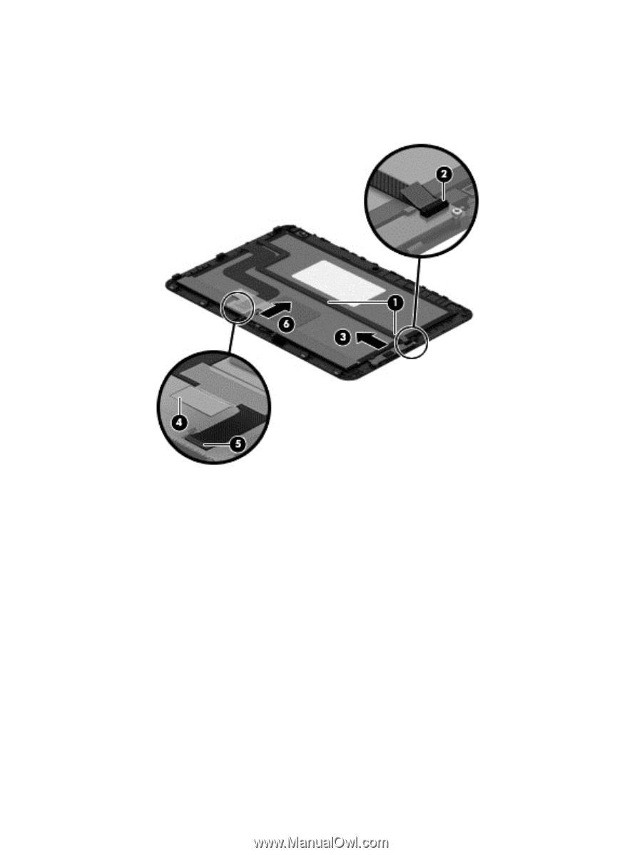
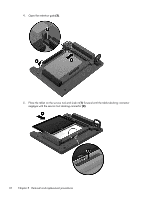
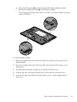
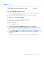
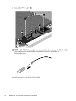
e. Release the ZIF connector (5) to which the display LVDS cable is attached, and then disconnect the display LVDS cable (6) from the display assembly. The TouchScreen and display LVDS cables are included in the Display Cable Kit, spare part number 718758-001. To install the display assembly: 1. Reconnect the display LVDS and TouchScreen cables to the respective ZIF connectors on the display assembly. 2. Reconnect the display LVDS and TouchScreen cables to the respective ZIF connectors on the system board. 3. Toe the left side of the display assembly into the left side of the bottom case. 4. Swing the right side of the display assembly down into the right side of the bottom case. 5. Firmly press all edges of the display assembly surface to ensure it is fully engaged with the bottom case. Tablet component replacement procedures 37
-
 1
1 -
2
-
3
-
4
-
5
-
6
-
7
-
8
-
9
-
10
-
11
-
12
-
13
-
14
-
15
-
16
-
17
-
18
-
19
-
20
-
21
-
22
-
23
-
24
-
25
-
26
-
27
-
28
-
29
-
30
-
31
-
32
-
33
-
34
-
35
-
36
-
37
-
38
-
39
-
 40
40 -
 41
41 -
 42
42 -
 43
43 -
 44
44 -
 45
45 -
 46
46 -
 47
47 -
 48
48 -
 49
49 -
 50
50 -
51
-
52
-
53
-
54
-
55
-
56
-
57
-
58
-
59
-
60
-
61
-
62
-
63
-
64
-
65
-
66
-
67
-
68
-
69
-
70
-
71
-
72
-
73
-
74
-
75
-
76
-
77
-
78
-
79
-
80
-
81
-
82
-
83
-
84
-
85
-
86
-
87
-
88
-
89
-
90
-
91
-
92
-
93
-
94
-
95
-
96
-
97
-
98
-
99
-
100
-
101
-
102
-
103
-
104
-
105
-
106
-
107
-
108
-
109
-
110
-
111
-
112
-
113
-
114
-
115
-
116
-
117
-
118
-
119
-
120
 |
 |