HP ElitePad 1000 HP ElitePad 1000 G2 Maintenance and Service Guide - Page 83
Battery connector board, Turn the front cover upside down with the top toward you.
 |
View all HP ElitePad 1000 manuals
Add to My Manuals
Save this manual to your list of manuals |
Page 83 highlights
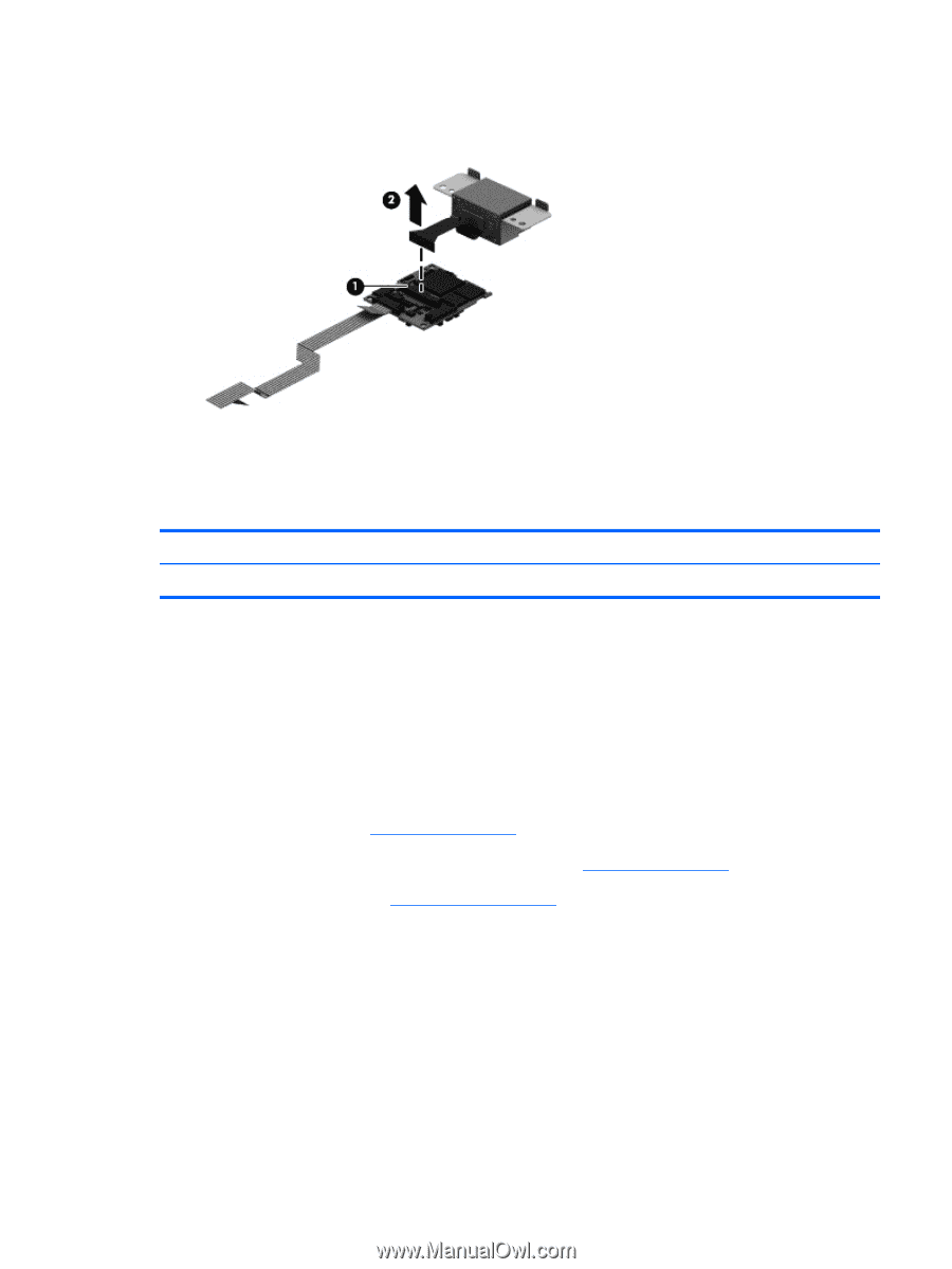
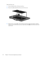
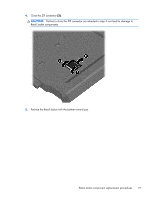
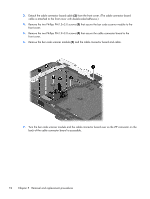
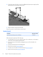
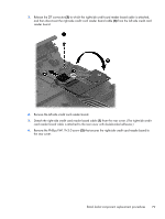
8. Release the ZIF connector (1) to which the bar code scanner module cable is attached, and then disconnect the bar code scanner module cable (2) from the cable connector board. Reverse this procedure to install the bar code scanner module and cable connector board. Battery connector board Description Battery connector board (includes cable) Spare part number 744033-001 Before removing the battery connector board, follow these steps: 1. Turn off the tablet. If you are unsure whether the tablet is off or in Hibernation, turn the tablet on, and then shut it down through the operating system. 2. Disconnect the power from the tablet by unplugging the power cord from the tablet or the Retail Jacket. 3. Disconnect all external devices from the Retail Jacket. 4. Remove the top cap (see Top cap on page 67). 5. If installed, remove the tablet from the Retail Jacket (see Top cap on page 67). 6. Remove the front cover (see Front cover on page 69). Remove the battery connector board: 1. Turn the front cover upside down with the top toward you. 2. Disconnect the battery connector board cable (1) from the system board. 3. Remove the two Phillips PM1.9×3.0 screws (2) that secure the battery connector board to the front cover. Retail Jacket component replacement procedures 75
-
 1
1 -
2
-
3
-
4
-
5
-
6
-
7
-
8
-
9
-
10
-
11
-
12
-
13
-
14
-
15
-
16
-
17
-
18
-
19
-
20
-
21
-
22
-
23
-
24
-
25
-
26
-
27
-
28
-
29
-
30
-
31
-
32
-
33
-
34
-
35
-
36
-
37
-
38
-
39
-
40
-
41
-
42
-
43
-
44
-
45
-
46
-
47
-
48
-
49
-
50
-
51
-
52
-
53
-
54
-
55
-
56
-
57
-
58
-
59
-
60
-
61
-
62
-
63
-
64
-
65
-
66
-
67
-
68
-
69
-
70
-
71
-
72
-
73
-
74
-
75
-
76
-
77
-
 78
78 -
 79
79 -
 80
80 -
 81
81 -
 82
82 -
 83
83 -
 84
84 -
 85
85 -
 86
86 -
 87
87 -
 88
88 -
89
-
90
-
91
-
92
-
93
-
94
-
95
-
96
-
97
-
98
-
99
-
100
-
101
-
102
-
103
-
104
-
105
-
106
-
107
-
108
-
109
-
110
-
111
-
112
-
113
-
114
-
115
-
116
-
117
-
118
-
119
-
120
 |
 |