HP ElitePad 1000 HP ElitePad 1000 G2 Maintenance and Service Guide - Page 82
and the cable connector board and cable., that secure the cable connector board to
 |
View all HP ElitePad 1000 manuals
Add to My Manuals
Save this manual to your list of manuals |
Page 82 highlights
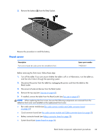
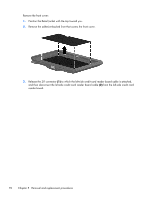
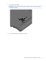
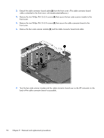
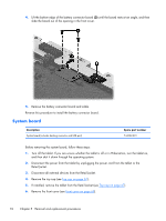
3. Detach the cable connector board cable (2) from the front cover. (The cable connector board cable is attached to the front cover with double-sided adhesive.) 4. Remove the two Phillips PM1.3×3.0 screws (3) that secure the bar code scanner module to the front cover. 5. Remove the two Phillips PM1.9×3.0 screws (4) that secure the cable connector board to the front cover. 6. Remove the bar code scanner module (5) and the cable connector board and cable. 7. Turn the bar code scanner module and the cable connector board over so the ZIF connector on the back of the cable connector board is accessible. 74 Chapter 5 Removal and replacement procedures
-
 1
1 -
2
-
3
-
4
-
5
-
6
-
7
-
8
-
9
-
10
-
11
-
12
-
13
-
14
-
15
-
16
-
17
-
18
-
19
-
20
-
21
-
22
-
23
-
24
-
25
-
26
-
27
-
28
-
29
-
30
-
31
-
32
-
33
-
34
-
35
-
36
-
37
-
38
-
39
-
40
-
41
-
42
-
43
-
44
-
45
-
46
-
47
-
48
-
49
-
50
-
51
-
52
-
53
-
54
-
55
-
56
-
57
-
58
-
59
-
60
-
61
-
62
-
63
-
64
-
65
-
66
-
67
-
68
-
69
-
70
-
71
-
72
-
73
-
74
-
75
-
76
-
 77
77 -
 78
78 -
 79
79 -
 80
80 -
 81
81 -
 82
82 -
 83
83 -
 84
84 -
 85
85 -
 86
86 -
 87
87 -
88
-
89
-
90
-
91
-
92
-
93
-
94
-
95
-
96
-
97
-
98
-
99
-
100
-
101
-
102
-
103
-
104
-
105
-
106
-
107
-
108
-
109
-
110
-
111
-
112
-
113
-
114
-
115
-
116
-
117
-
118
-
119
-
120
 |
 |
3.
Detach the cable connector board cable
(2)
from the front cover. (The cable connector board
cable is attached to the front cover with double-sided adhesive.)
4.
Remove the two Phillips PM1.3×3.0 screws
(3)
that secure the bar code scanner module to the
front cover.
5.
Remove the two Phillips PM1.9×3.0 screws
(4)
that secure the cable connector board to the
front cover.
6.
Remove the bar code scanner module
(5)
and the cable connector board and cable.
7.
Turn the bar code scanner module and the cable connector board over so the ZIF connector on the
back of the cable connector board is accessible.
74
Chapter 5
Removal and replacement procedures