HP ElitePad 1000 HP ElitePad 1000 G2 Maintenance and Service Guide - Page 85
Slide the docking connector, Remove the system board
 |
View all HP ElitePad 1000 manuals
Add to My Manuals
Save this manual to your list of manuals |
Page 85 highlights
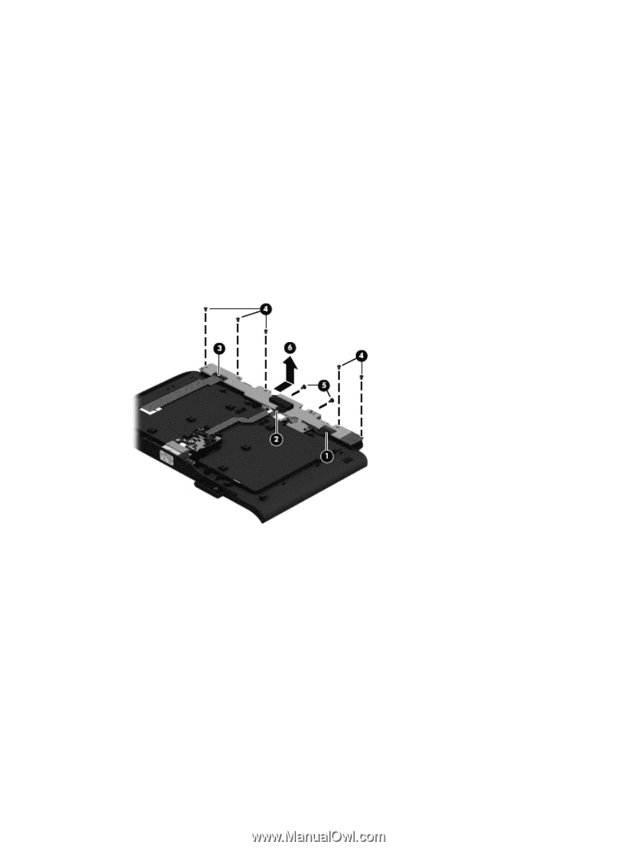
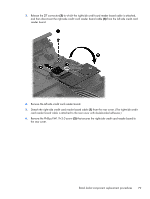
Remove the system board: 1. Turn the front cover upside down with the top toward you. 2. Disconnect the battery connector board cable (1) from the system board. 3. Release the ZIF connector (2) to which the cable connector board cable is attached, and then disconnect the cable connector board cable from the system board. 4. Release the ZIF connector (3) to which the credit card reader/left board cable is attached, and then disconnect the credit card reader/left board cable from the system board. 5. Remove the five Phillips PM1.9×3.0 screws (4) that secure the system board to the front cover. 6. Remove the two Phillips PM1.9×3.0 screws (5) that secure the system board to the front cover. 7. Slide the docking connector (6) out of the opening in the front cover, and then remove the system board. Reverse this procedure to install the system board. Retail Jacket component replacement procedures 77
-
 1
1 -
2
-
3
-
4
-
5
-
6
-
7
-
8
-
9
-
10
-
11
-
12
-
13
-
14
-
15
-
16
-
17
-
18
-
19
-
20
-
21
-
22
-
23
-
24
-
25
-
26
-
27
-
28
-
29
-
30
-
31
-
32
-
33
-
34
-
35
-
36
-
37
-
38
-
39
-
40
-
41
-
42
-
43
-
44
-
45
-
46
-
47
-
48
-
49
-
50
-
51
-
52
-
53
-
54
-
55
-
56
-
57
-
58
-
59
-
60
-
61
-
62
-
63
-
64
-
65
-
66
-
67
-
68
-
69
-
70
-
71
-
72
-
73
-
74
-
75
-
76
-
77
-
78
-
79
-
 80
80 -
 81
81 -
 82
82 -
 83
83 -
 84
84 -
 85
85 -
 86
86 -
 87
87 -
 88
88 -
 89
89 -
 90
90 -
91
-
92
-
93
-
94
-
95
-
96
-
97
-
98
-
99
-
100
-
101
-
102
-
103
-
104
-
105
-
106
-
107
-
108
-
109
-
110
-
111
-
112
-
113
-
114
-
115
-
116
-
117
-
118
-
119
-
120
 |
 |