HP ElitePad 1000 HP ElitePad 1000 G2 Maintenance and Service Guide - Page 63
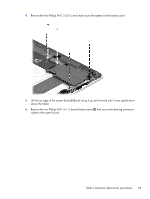
that secure the docking connector, cable to the system board.
 |
View all HP ElitePad 1000 manuals
Add to My Manuals
Save this manual to your list of manuals |
Page 63 highlights
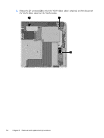
4. Remove the five Phillips PM1.3×2.0 screws that secure the battery to the bottom cover. 5. Lift the top edge of the system board (1) and swing it up and forward until it rests upside down above the tablet. 6. Remove the two Phillips PM1.3×1.5 broad head screws (2) that secure the docking connector cable to the system board. Tablet component replacement procedures 55
-
 1
1 -
2
-
3
-
4
-
5
-
6
-
7
-
8
-
9
-
10
-
11
-
12
-
13
-
14
-
15
-
16
-
17
-
18
-
19
-
20
-
21
-
22
-
23
-
24
-
25
-
26
-
27
-
28
-
29
-
30
-
31
-
32
-
33
-
34
-
35
-
36
-
37
-
38
-
39
-
40
-
41
-
42
-
43
-
44
-
45
-
46
-
47
-
48
-
49
-
50
-
51
-
52
-
53
-
54
-
55
-
56
-
57
-
 58
58 -
 59
59 -
 60
60 -
 61
61 -
 62
62 -
 63
63 -
 64
64 -
 65
65 -
 66
66 -
 67
67 -
 68
68 -
69
-
70
-
71
-
72
-
73
-
74
-
75
-
76
-
77
-
78
-
79
-
80
-
81
-
82
-
83
-
84
-
85
-
86
-
87
-
88
-
89
-
90
-
91
-
92
-
93
-
94
-
95
-
96
-
97
-
98
-
99
-
100
-
101
-
102
-
103
-
104
-
105
-
106
-
107
-
108
-
109
-
110
-
111
-
112
-
113
-
114
-
115
-
116
-
117
-
118
-
119
-
120
 |
 |
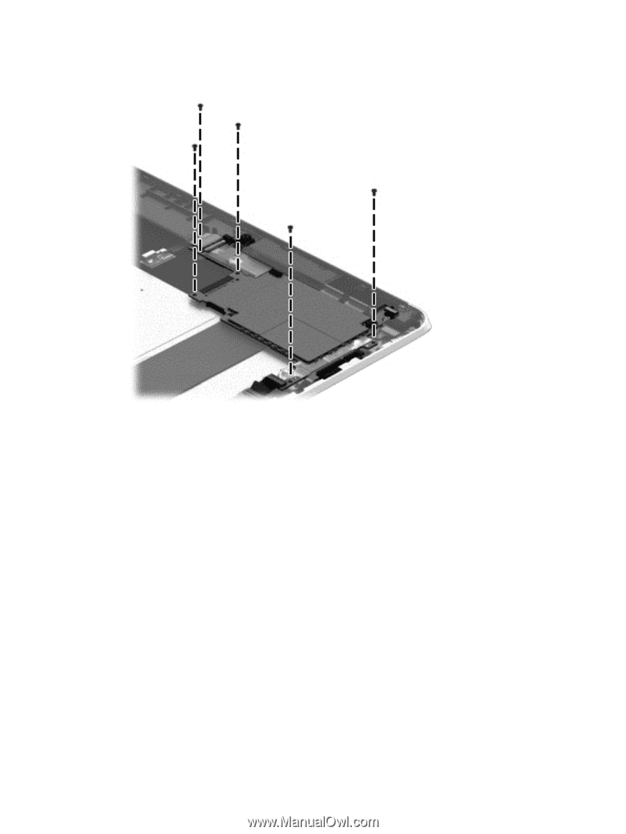
4.
Remove the five Phillips PM1.3×2.0 screws that secure the battery to the bottom cover.
5.
Lift the top edge of the system board
(1)
and swing it up and forward until it rests upside down
above the tablet.
6.
Remove the two Phillips PM1.3×1.5 broad head screws
(2)
that secure the docking connector
cable to the system board.
Tablet component replacement procedures
55