HP LD4730 User Guide - Page 22
Setting up the display, Label, Function
 |
View all HP LD4730 manuals
Add to My Manuals
Save this manual to your list of manuals |
Page 22 highlights
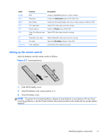
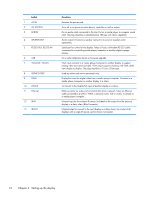
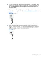
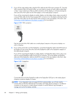
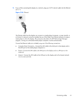
Label 1 AC-IN 2 AC SWITCH 3 LINE-IN 4 SPEAKER-OUT 5 RS232-OUT, RS232-IN 6 USB 7 VGA-OUT, VGA-IN 8 SERVICE PORT 9 DP-IN 10 DP-OUT 11 Ethernet 12 IR-IN 13 IR-OUT Function Receives the power cord. Turns off or on power to entire device, controller as well as screen. For an audio cable connected to the Line Out on a media player or computer sound card. The plug should be a standard-sized, TRS-type with stereo capability. Audio output for bare-wire speaker connection to external speakers (sold separately). Serial port for control of the display. Takes a 9-pin, null-modem RS-232 cable connected to a controlling media player/computer or another digital signage display. For a color-calibration device or firmware upgrade. VGA input connects to a media player/computer or another display to support analog video and command data. VGA output supports chaining with VGA cables from display to display. The plug should be a 15-pin, D-Sub type. Used by authorized service personnel only. DisplayPort input for digital video from a media player/computer. Connects to a media player/computer or another display in a chain. To connect to the DisplayPort input of another display in a chain. RJ45 connector for video and command data from a network. Takes an Ethernet cable connected to a LAN or WAN; a network router, hub or switch; or directly to a media player/computer. Infrared input for the external IR sensor (included) or the output from the previous display in a daisy chain (Blue Connector). Infrared output to connect to the next display in a daisy chain, for control of all displays with a single IR remote control (Green Connector). 16 Chapter 3 Setting up the display
-
 1
1 -
2
-
3
-
4
-
5
-
6
-
7
-
8
-
9
-
10
-
11
-
12
-
13
-
14
-
15
-
16
-
 17
17 -
 18
18 -
 19
19 -
 20
20 -
 21
21 -
 22
22 -
 23
23 -
 24
24 -
 25
25 -
 26
26 -
 27
27 -
28
-
29
-
30
-
31
-
32
-
33
-
34
-
35
-
36
-
37
-
38
-
39
-
40
-
41
-
42
-
43
-
44
-
45
-
46
-
47
-
48
-
49
-
50
-
51
-
52
-
53
-
54
-
55
-
56
-
57
-
58
-
59
-
60
-
61
-
62
-
63
-
64
-
65
-
66
-
67
-
68
-
69
-
70
-
71
-
72
-
73
-
74
-
75
 |
 |