HP LD4730 User Guide - Page 25
HP LD4730 Manual
 |
View all HP LD4730 manuals
Add to My Manuals
Save this manual to your list of manuals |
Page 25 highlights
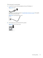
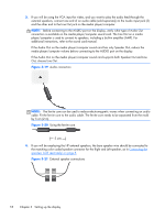
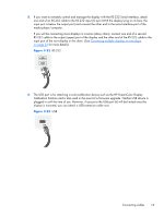
5. If you want to remotely control and manage the display with the RS-232 Serial interface, attach one end of an RS-232 cable to the RS-232 input (5) port (With the display lying on its face, the input port is below the output port) and connect the other end to the serial interface port of the media player/computer. If you will be connecting more displays in a series (daisy chain), connect one end of a second RS-232 cable to the output (upper) port of the display and the other end of the RS-232 cable to the input port of the next display in the chain. (See Connecting multiple displays to one player on page 24 for more details). Figure 3-22 RS-232 6. The USB port is for attaching a color-calibration device such as the HP DreamColor Display Calibration Solution and is also used in the event of a firmware upgrade. Neither USB device is plugged in until the time of use. However, if access to the USB port (6) will be limited once the display is mounted, you can attach a USB extension cable now. Figure 3-23 USB Connecting cables 19
-
 1
1 -
2
-
3
-
4
-
5
-
6
-
7
-
8
-
9
-
10
-
11
-
12
-
13
-
14
-
15
-
16
-
17
-
18
-
19
-
 20
20 -
 21
21 -
 22
22 -
 23
23 -
 24
24 -
 25
25 -
 26
26 -
 27
27 -
 28
28 -
 29
29 -
 30
30 -
31
-
32
-
33
-
34
-
35
-
36
-
37
-
38
-
39
-
40
-
41
-
42
-
43
-
44
-
45
-
46
-
47
-
48
-
49
-
50
-
51
-
52
-
53
-
54
-
55
-
56
-
57
-
58
-
59
-
60
-
61
-
62
-
63
-
64
-
65
-
66
-
67
-
68
-
69
-
70
-
71
-
72
-
73
-
74
-
75
 |
 |
