HP LD4730 User Guide - Page 34
Daisy chain connection - External IR Sensor
 |
View all HP LD4730 manuals
Add to My Manuals
Save this manual to your list of manuals |
Page 34 highlights
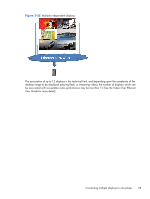
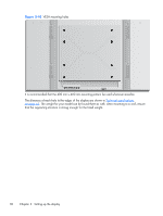
If using a Network connection, just attach each display to a network hub or access point using a CAT-5 cable, and HP Network Sign Manager will locate each network attached display. The HP Network Sign Manager will allow users to select any display or assigned group of displays to manage and control. If the display is already attached to the network for VOE, there is no further action required. The HP Network Sign Manager will detect the displays via its search function (See the HP Network Sign Manager Users Guide for more details). Figure 3-37 Daisy chain connection - RS232-C RS-232C (CONTROL) OUT RS-232C (CONTROL) OUT RS-232C (CONTROL) OUT RS-232C (CONTROL) OUT IN IN IN IN 1 2 3 4 Multiple displays may also be controlled and managed with the IR Remote Control. Since the primary use of the displays is for video walls, use of the External IR Sensor is needed to provide the best IR remote control responsiveness. Connect the supplied External IR Sensor to the IR IN (Blue) jack. Take one end of the supplied IR Daisy Chain Cable and connect it to the IR OUT (Green) jack of the display and connect the other end of the cable to the IR IN jack of the next display as shown in Figure 3-38 Daisy chain connection - External IR Sensor on page 28. Once all the displays are connected, the user can issue any OSD command with the IR Remote Control to all the displays at once (for example, turn the displays ON or OFF, set Picture Mode to VIVID, etc.), or the user can indicate a single display in the wall to control by selecting the ID of the appropriate display and then issuing any OSD command with the IR Remote Control. See Navigating with the infrared remote control on page 37 for more detail. Figure 3-38 Daisy chain connection - External IR Sensor NOTE: The number of displays that can be connected by daisy chain to one media player/computer might vary depending on the signal status and cable loss. If the signal status is good, and there is no cable loss, it is possible to connect up to twenty-five displays in a daisy chain from one media player/ computer. If you are going to play video that is copy protected with High-bandwidth Digital Content Protection (HDCP), you must use DisplayPort as the video source, and you are limited to a maximum of six displays in the daisy chain which can support HDCP. When using Tile Mode, the display ID can be set in the display OSD with the IR Remote Control, the display control panel, or for Network attached displays, the display ID can be set with the HP Network 28 Chapter 3 Setting up the display
-
 1
1 -
2
-
3
-
4
-
5
-
6
-
7
-
8
-
9
-
10
-
11
-
12
-
13
-
14
-
15
-
16
-
17
-
18
-
19
-
20
-
21
-
22
-
23
-
24
-
25
-
26
-
27
-
28
-
 29
29 -
 30
30 -
 31
31 -
 32
32 -
 33
33 -
 34
34 -
 35
35 -
 36
36 -
 37
37 -
 38
38 -
 39
39 -
40
-
41
-
42
-
43
-
44
-
45
-
46
-
47
-
48
-
49
-
50
-
51
-
52
-
53
-
54
-
55
-
56
-
57
-
58
-
59
-
60
-
61
-
62
-
63
-
64
-
65
-
66
-
67
-
68
-
69
-
70
-
71
-
72
-
73
-
74
-
75
 |
 |
