HP LD4730 User Guide - Page 41
Controlling displays with IR Daisy Chain, Setting up IR Daisy Chain
 |
View all HP LD4730 manuals
Add to My Manuals
Save this manual to your list of manuals |
Page 41 highlights
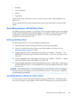
● Resolution ● Color Temperature ● Speaker ● Aspect Ratio All other OSD settings need only be set once in order for the new value to apply regardless of the video source. You can operate the OSD using the infrared remote control or the control panel on the back of the display. Controlling displays with IR Daisy Chain The display provides the capability of using IR Daisy Chain to enable selectable control of the displays locally, using the IR Remote Control when the displays are mounted in a video wall. You may control one display at a time by selecting the ID of the display, or you may control all the displays simultaneously by selecting an ID of "00". Setting up IR Daisy Chain The following describes how to set up the displays for IR Daisy Chain 1. Insert the External IR Sensor into the IR IN (blue) jack at the back of the display 2. Using the included IR Daisy Chain Cable, connect all the displays in the video wall. See Connecting cables on page 15 for details. 3. Using the IR Remote Control or the display control buttons, go to MENU → OPTION 2 → SET MONITOR ID and set the unique ID number (number between 1 and 25) for each display in the video wall 4. Using the IR Remote Control or the display control buttons, go to MENU → OPTION 2 → IR OUT and chose ENABLE for each of the displays in the video wall 5. Using the double sided tape, locate the External IR Sensor away in a spot where it will be easy to point the IR Remote Control. It is recommended that the sensor be located at the top left or right of the video wall. NOTE: Care should be taken to avoid locating the sensor next to the bottom of any of the displays where the IR sensor of the display could sense the IR Remote Control or where the sensor might block the viewing area of any display. Controlling displays with the IR remote control Point the IR remote control at the External IR Sensor and press the MENU button. The IR Daisy Chain home menu will appear on each display, with the Monitor ID displayed so you can easily identify the Using the On-Screen Display menu 35
-
 1
1 -
2
-
3
-
4
-
5
-
6
-
7
-
8
-
9
-
10
-
11
-
12
-
13
-
14
-
15
-
16
-
17
-
18
-
19
-
20
-
21
-
22
-
23
-
24
-
25
-
26
-
27
-
28
-
29
-
30
-
31
-
32
-
33
-
34
-
35
-
 36
36 -
 37
37 -
 38
38 -
 39
39 -
 40
40 -
 41
41 -
 42
42 -
 43
43 -
 44
44 -
 45
45 -
 46
46 -
47
-
48
-
49
-
50
-
51
-
52
-
53
-
54
-
55
-
56
-
57
-
58
-
59
-
60
-
61
-
62
-
63
-
64
-
65
-
66
-
67
-
68
-
69
-
70
-
71
-
72
-
73
-
74
-
75
 |
 |
