HP LD4730 User Guide - Page 36
that the supporting structure is strong enough for the listed weight.
 |
View all HP LD4730 manuals
Add to My Manuals
Save this manual to your list of manuals |
Page 36 highlights
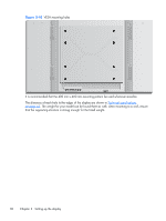
Figure 3-40 VESA mounting holes 1 1 2 2 2 2 1 1 It is recommended that the 400 mm x 400 mm mounting pattern be used whenever possible. The distances of each hole to the edges of the display are shown in Technical specifications on page 63. The weight for your model can be found there as well; when mounting to a wall, ensure that the supporting structure is strong enough for the listed weight. 30 Chapter 3 Setting up the display
-
 1
1 -
2
-
3
-
4
-
5
-
6
-
7
-
8
-
9
-
10
-
11
-
12
-
13
-
14
-
15
-
16
-
17
-
18
-
19
-
20
-
21
-
22
-
23
-
24
-
25
-
26
-
27
-
28
-
29
-
30
-
 31
31 -
 32
32 -
 33
33 -
 34
34 -
 35
35 -
 36
36 -
 37
37 -
 38
38 -
 39
39 -
 40
40 -
 41
41 -
42
-
43
-
44
-
45
-
46
-
47
-
48
-
49
-
50
-
51
-
52
-
53
-
54
-
55
-
56
-
57
-
58
-
59
-
60
-
61
-
62
-
63
-
64
-
65
-
66
-
67
-
68
-
69
-
70
-
71
-
72
-
73
-
74
-
75
 |
 |
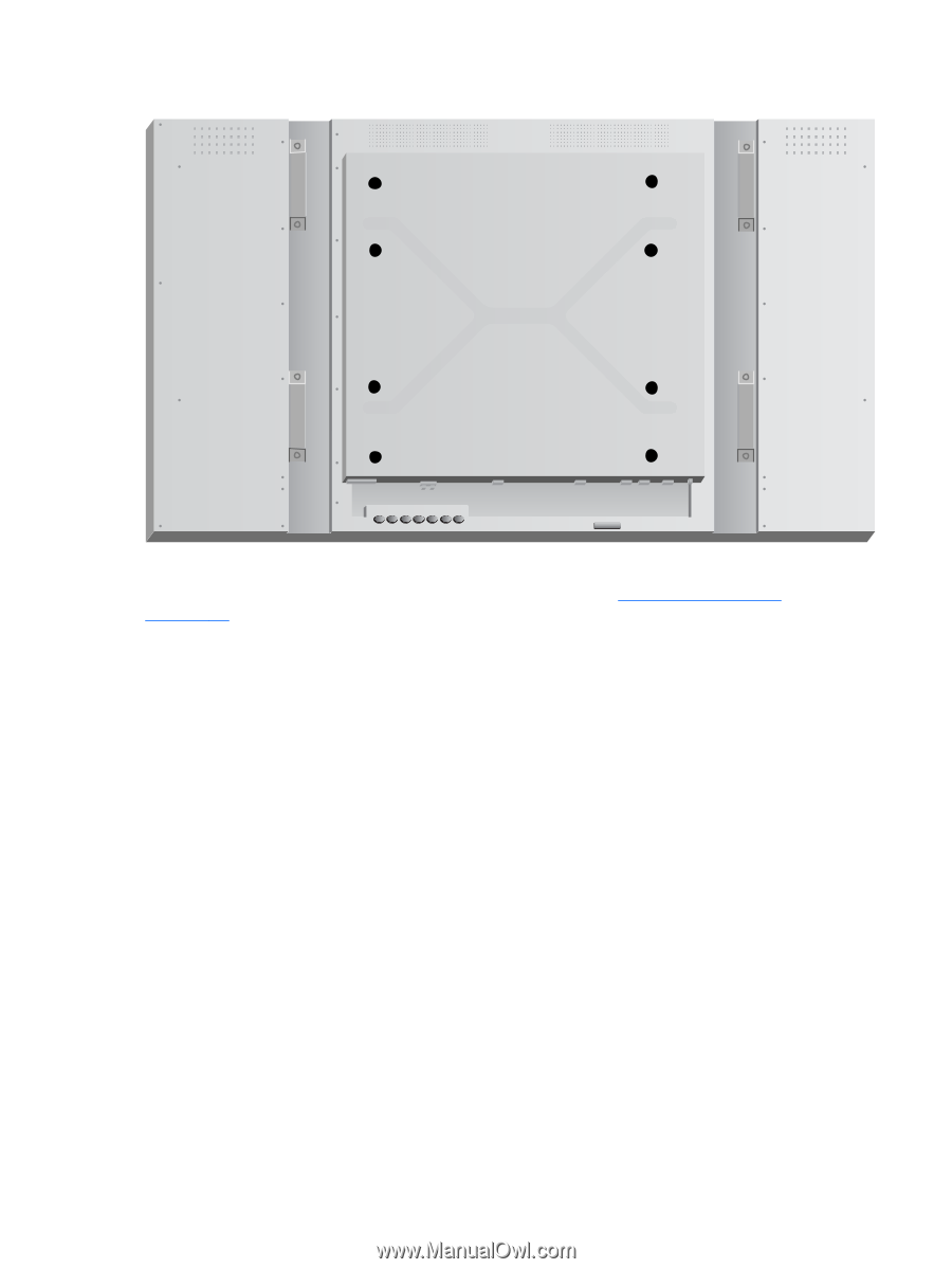
Figure 3-40
VESA mounting holes
1
2
2
1
2
1
1
2
It is recommended that the 400 mm x 400 mm mounting pattern be used whenever possible.
The distances of each hole to the edges of the display are shown in
Technical specifications
on page
63
. The weight for your model can be found there as well; when mounting to a wall, ensure
that the supporting structure is strong enough for the listed weight.
30
Chapter 3
Setting up the display