HP ML150 HP ProLiant ML150 G6 Server Maintenance and Service Guide - Page 24
Removal and replacement procedures, Required tools, Hardware configuration information - proliant memory
 |
UPC - 884420743644
View all HP ML150 manuals
Add to My Manuals
Save this manual to your list of manuals |
Page 24 highlights
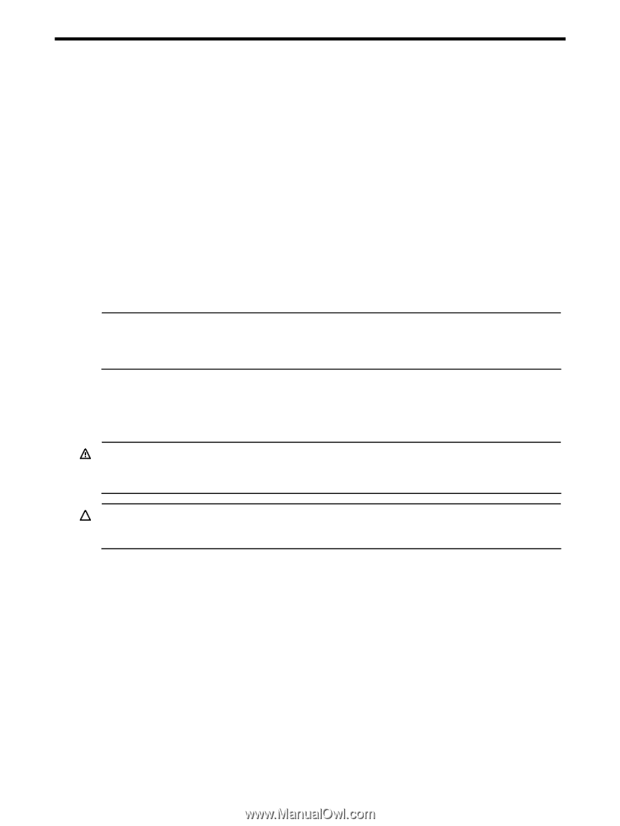
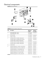
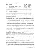
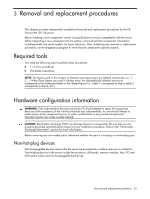
3 Removal and replacement procedures This chapter provides subassembly/module-level removal and replacement procedures for the HP ProLiant ML150 G6 server. Before installing a new component, review its specifications to ensure compatibility with the server. When integrating a new component into the system, record all pertinent component information, including model and serial number, for future reference. After completing any removal or replacement procedure, run the diagnostics program to verify that all components operate properly. Required tools You need the following tools to perform these procedures: • T-15 Torx screwdriver • Flat-blade screwdriver NOTE: The figures used in this chapter to illustrate procedural steps are labeled numerically (i.e., 1, 2...). When these figures are used in substep items, the alphabetically labeled instructions correspond to the numbered labels on the related figure (i.e., Label 1 corresponds to step a, label 2 corresponds to step b, etc.). Hardware configuration information WARNING: Only authorized technicians trained by HP should attempt to repair this equipment. Because of the complexity of the individual boards and subassemblies, no one should attempt to make repairs at the component level or to make modifications to any printed wiring board. Improper repairs can create a safety hazard. CAUTION: Electrostatic discharge (ESD) can damage electronic components. Be sure that you are properly grounded (earthed) before beginning any installation procedure. Refer to the "Electrostatic Discharge Information" section for more information. Before removing any serviceable parts, determine whether the part is a hot-plug or non-hot-plug type. Non-hot-plug devices Non-hot-pluggable devices require that the server be powered down before removal or installation. Non-hot-plug devices in the server include the processor, all boards, memory modules, fans, PCI and IPMI option cards, and non-hot-pluggable hard drives. Removal and replacement procedures 24
-
 1
1 -
2
-
3
-
4
-
5
-
6
-
7
-
8
-
9
-
10
-
11
-
12
-
13
-
14
-
15
-
16
-
17
-
18
-
 19
19 -
 20
20 -
 21
21 -
 22
22 -
 23
23 -
 24
24 -
 25
25 -
 26
26 -
 27
27 -
 28
28 -
 29
29 -
30
-
31
-
32
-
33
-
34
-
35
-
36
-
37
-
38
-
39
-
40
-
41
-
42
-
43
-
44
-
45
-
46
-
47
-
48
-
49
-
50
-
51
-
52
-
53
-
54
-
55
-
56
-
57
-
58
-
59
-
60
-
61
-
62
-
63
-
64
-
65
-
66
-
67
-
68
-
69
-
70
-
71
-
72
-
73
-
74
-
75
-
76
-
77
-
78
-
79
-
80
-
81
-
82
-
83
-
84
-
85
-
86
-
87
-
88
-
89
-
90
-
91
-
92
-
93
-
94
-
95
-
96
-
97
-
98
-
99
-
100
-
101
-
102
-
103
-
104
-
105
-
106
 |
 |