HP ML150 HP ProLiant ML150 G6 Server Maintenance and Service Guide - Page 60
Replacing the system board
 |
UPC - 884420743644
View all HP ML150 manuals
Add to My Manuals
Save this manual to your list of manuals |
Page 60 highlights
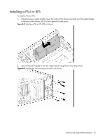
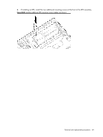
Replacing the system board To replace the system board, proceed as follows: 1. Lower the system board into the chassis, tilting the rear edge down first so that the rear port connectors align with the rear panel cutouts, then lower the front edge down until it is level. Ensure that the mounting holes on the board are aligned with the screw taps on the chassis. 2. Insert and tighten the 11 mounting screws. 3. Install the processor heatsink(s) as described ion the section "Replacing the processor." 4. Install the system fans as described in the section "System fans." 5. Install any expansion cards as described in the section "Installing an expansion card." 6. Return the server to an upright position. 7. Replace the access panel. 8. Connect the power supply cord(s). End of procedure. Removal and replacement procedures 60
-
 1
1 -
2
-
3
-
4
-
5
-
6
-
7
-
8
-
9
-
10
-
11
-
12
-
13
-
14
-
15
-
16
-
17
-
18
-
19
-
20
-
21
-
22
-
23
-
24
-
25
-
26
-
27
-
28
-
29
-
30
-
31
-
32
-
33
-
34
-
35
-
36
-
37
-
38
-
39
-
40
-
41
-
42
-
43
-
44
-
45
-
46
-
47
-
48
-
49
-
50
-
51
-
52
-
53
-
54
-
 55
55 -
 56
56 -
 57
57 -
 58
58 -
 59
59 -
 60
60 -
 61
61 -
 62
62 -
 63
63 -
 64
64 -
 65
65 -
66
-
67
-
68
-
69
-
70
-
71
-
72
-
73
-
74
-
75
-
76
-
77
-
78
-
79
-
80
-
81
-
82
-
83
-
84
-
85
-
86
-
87
-
88
-
89
-
90
-
91
-
92
-
93
-
94
-
95
-
96
-
97
-
98
-
99
-
100
-
101
-
102
-
103
-
104
-
105
-
106
 |
 |
